7
Installation
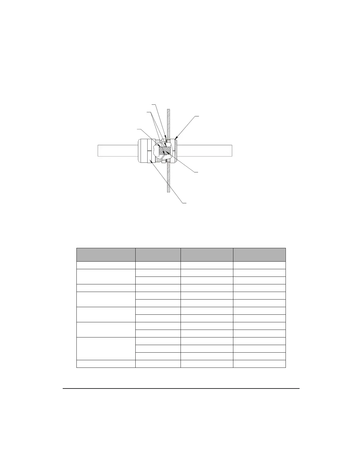
Figure 3: Assembly Drawing for Shielded Cable Grommet Kits Listed in Table Below.
Cable Type Cable Model
Shielded Cable Grommet
Kit Model
Actual Hole Size
Motor Cable, 16 Ga CMDS CGS-047 0.8125 or 13/16"
Motor Cable, 12 Ga
CMMS CGS-069 1.125 or 1 1/8"
4X12SS CGS-069 1.125 or 1 1/8"
Motor Cable, 8 Ga CMLS CGS-098 1.5 or 1 1/2"
Feedback Cable
CFOS CGS-047 0.8125 or 13/16"
MGFS CGS-047 0.8125 or 13/16"
Flex Motor Cable, 16 Ga
CMDF CGS-047 0.8125 or 13/16"
4X16SF CGS-047 0.8125 or 13/16"
Flex Motor Cable, 12 Ga
CMMF CGS-069 1.125 or 1 1/8"
4X12SF CGS-069 1.125 or 1 1/8"
Flex Feedback Cable
CFCF CGS-069 1.125 or 1 1/8"
CFOF-A CGS-069 1.125 or 1 1/8"
MGFF CGS-069 1.125 or 1 1/8"
External Encoder ENCO CGS-047 0.8125 or 13/16"
After tighten lock nut and positioning cable
so that spring contacts are contacting the
cable shield, tighten cable seal housing.
Remove 1/2 to 1 inches of cable jacket.
The Spring Contacts will make a continuous
electrical path from the shield of the cable to
equipment ground.
When Lock Nut is tighten to inside of
enclosure, lock nut will cut through varnished,
anodized and powder coated finishes.
Tighten lock nut so that is cuts through
finish and into housing.
Outside Enclosure
Cable Shielding
Spring Contacts
O-Ring seals against outside of enclosure
to meet IP 68 (comparable to NEMA 6)
Inside Enclosure
Artisan Technology Group - Quality Instrumentation ... Guaranteed | (888) 88-SOURCE | www.artisantg.com
 Loading...