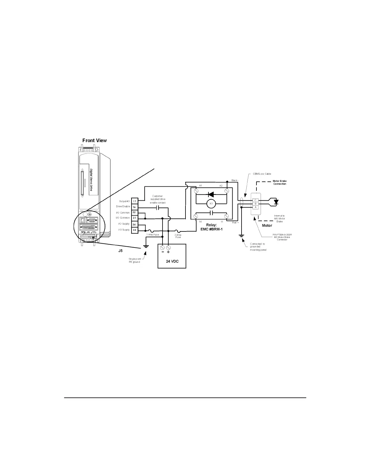
EasyManuals Logo
Home>Emerson>DC Drives>Control Techniques EN Series

Emerson Control Techniques EN Series Installation Manual

Emerson Control Techniques EN Series
110 pages
To Next Page IconTo Next Page
To Previous Page IconTo Previous Page
Page #38 background imageLoading...
Page #38 background image
21
Installation
Motor Brake Wiring
Motors equipped with brakes have a three-pin MS style connector. The brake power cable
(model CBMS-XXX) has an MS style connector on the motor end and three wire leads on the
amplifier end (see the following wiring diagrams).
You must provide a DC power supply rated at +24 VDC with a 2 amp minimum current
capacity for the brake. If you use this voltage source to power other accessories such as I/O
or more than one brake, you must increase its current capability.
Figure 16: EN Brake Wiring Diagram using the Command Connector
Artisan Technology Group - Quality Instrumentation ... Guaranteed | (888) 88-SOURCE | www.artisantg.com

Other manuals for Emerson Control Techniques EN Series

Questions and Answers:

Question and Answer IconNeed help?

Do you have a question about the Emerson Control Techniques EN Series and is the answer not in the manual?

Emerson Control Techniques EN Series Specifications

General IconGeneral
BrandEmerson
ModelControl Techniques EN Series
CategoryDC Drives
LanguageEnglish

Related product manuals