1592001440 XC645CX GB r3.4 31.10.2017.docx XC645CX 8/54
5. WIRING & ELECTRICAL CONNECTIONS
5.1 General warnings
Before connecting cables make sure the power supply complies with the instrument’s
requirements.
Separate the probe cables from the power supply cables, from the outputs and the power
connections.
Do not exceed the maximum current allowed on each relay 3A resistive, see also Technical
Features, in case of heavier loads use a suitable external relay.
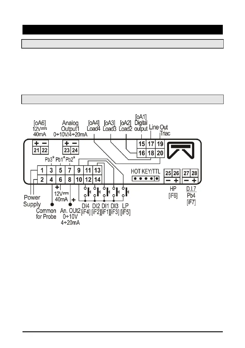
5.2 Wiring connections
Power supply: model at 12Vac/dc supply: use terminals 1-2
Power supply: model at 124Vac/dc supply: use terminals 1-2
- Always use a class 2 transformer with minimum power 5VA such as TF5.
- Terminals [21-22], [23-24], [25-26], [27-28] are provided with JST 2 PINS connectors, they
require the CABCJ15 (1,5mt) or CABCJ30 (3mt) wiring cables
 Loading...