Other Messages E2 MODBUS Network Wiring • 21
17 E2 MODBUS Network Wiring
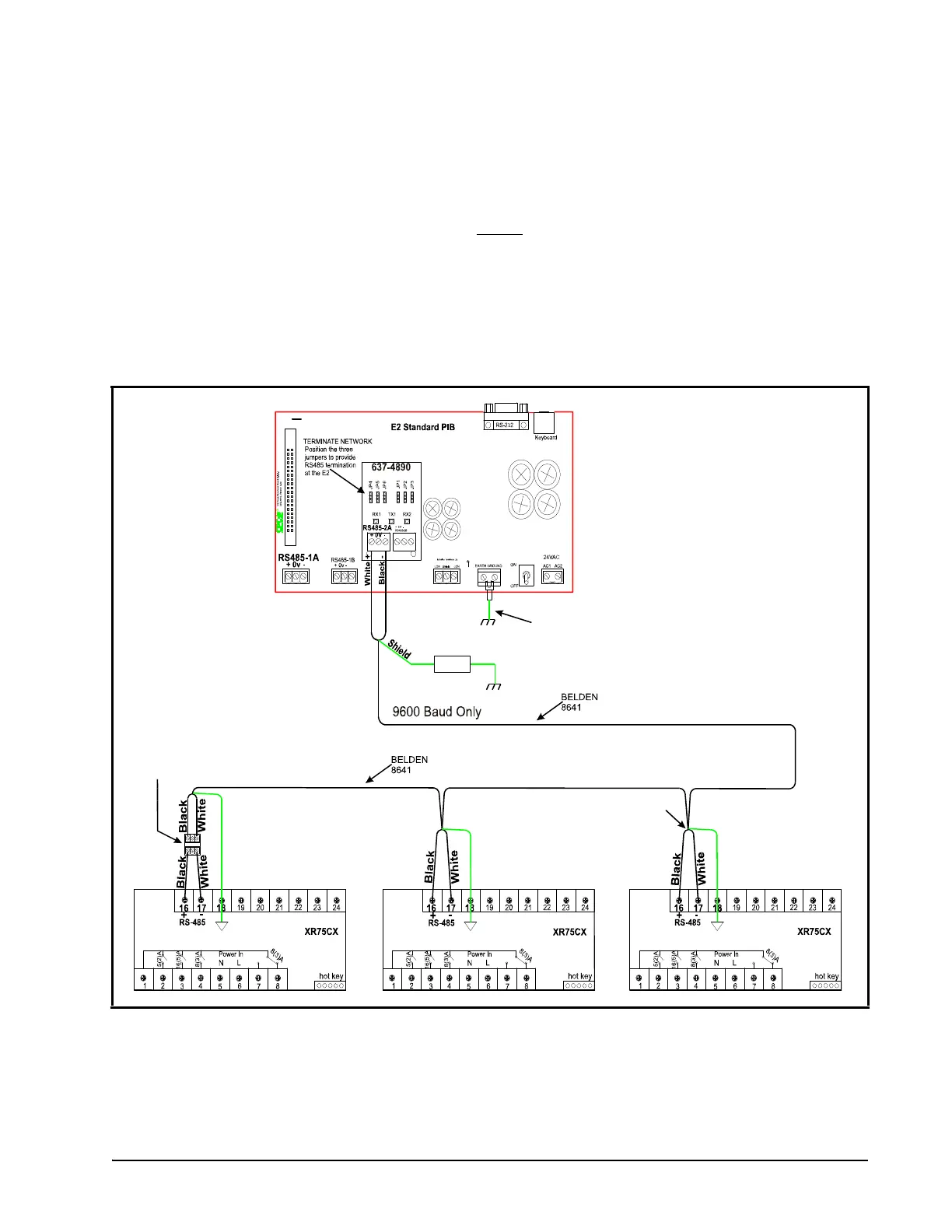
• Connect the MODBUS Network to the RS485 Connector on the E2 PIB board (Belden 8641 recommended).
• Note to wire the RS485 +/- polarity at the E2 in the reverse
of the XR75CX devices.
• Position the three termination jumpers to the UP (terminated) position to provide RS485 termination at the E2.
• Do not connect the shield of the MODBUS network to the E2 PIB center terminal. Instead, use a 100 ohm 1/2 watt
resistor to connect the MODBUS cable shield to earth ground.
• At each XR75CX device, wire the MODBUS cable to the RS485 +/- terminals and connect the MODBUS shield to
the pin 18 terminal.
• Terminate the end of the MODBUS network at the last XR75CX device on the daisy chain with the MODBUS
termination block (P/N 535-2711), or by connecting a 150 ohm resistor between the MODBUS +/- terminals.
Refer to Appendix A - Alternate MODBUS COM Wiring Method for E2, XR, XM, and XEV Devices
(Technical Bulletin P/N 026-4148).
Figure 17-1 - XR75CX to E2 MODBUS Network Wiring
100 Ohm
½ Watt
Shield
Shield
Shield
MODBUS TERMINATION
BLOCK 535-2711 150 ohm
Terminate last device only
COM4
REVERSE POLARITY OF +/- ON RS-485
CABLE FROM E2 TO DEVICE
*Note that for E2 Enhanced PIB
boards, the RS-485 connection
can be wired on COM 2, COM 4,
or COM 6 port.

 Loading...