6 Chapter 3 Installation
EC20 Series PLC User Manual
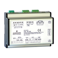
Pull out the Clip
of DIN rail
Snap the clip of the DIN rail
DIN rail with 35mm width
DIN rail stop
DIN rail stop
Figure 3-2 Installing a PLC onto a standard rail
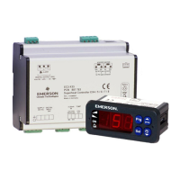
Under the conditions with great impact, you should mount the PLC on a panel using the screw installation. Using four
fix screws through the four Φ4 mounting holes on the enclosure of the PLC (while EC20-2012BR/BT has only two Φ4
fix screws) to fix the PLC on the back panel of the electric cabinet, as shown in the Figure 3-3.
4 mounting holes
M3 fix screw
M3 fix screw
Figure 3-2 Installing a PLC onto a panel with fix screws
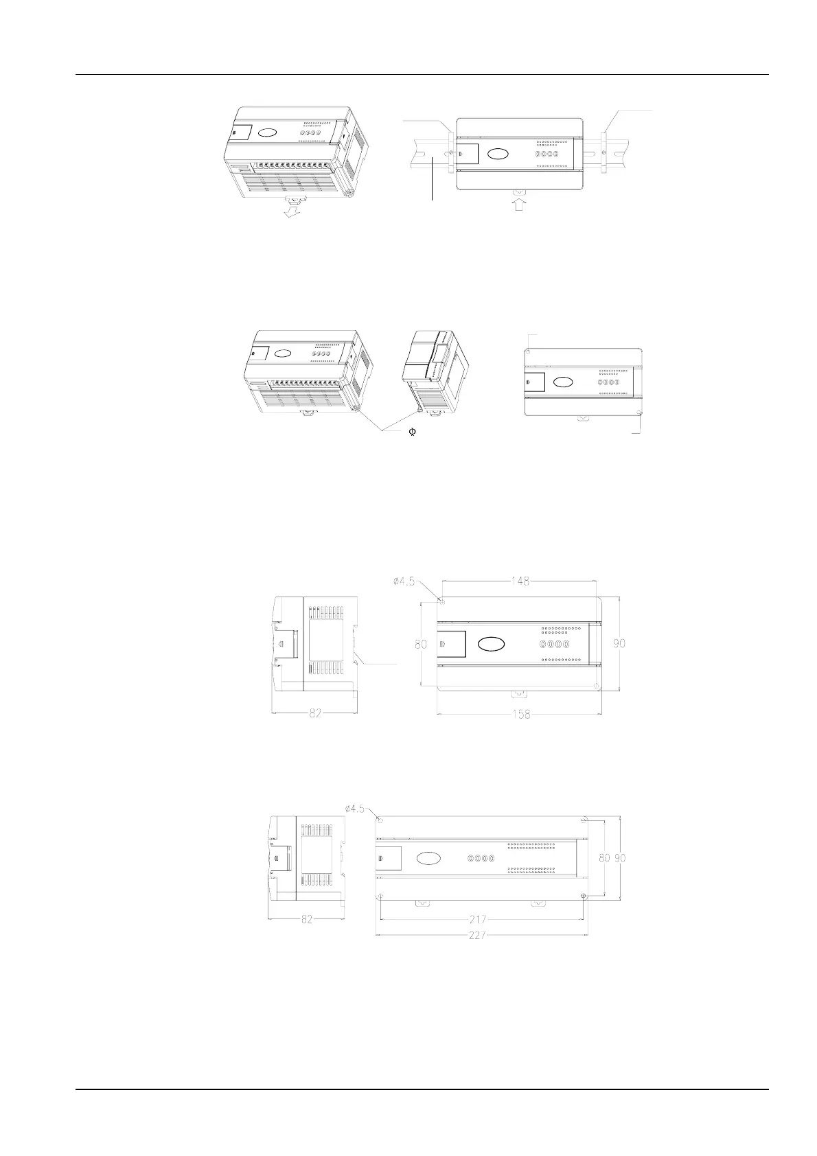
3.4 Installation Dimensions
1. The dimensions for the outline and mounting holes of EC20-2012BR and EC20-2012BT are shown in the Figure
3-4:
DIN rail
(35mm)
Figure 3-4 Dimensions of outline and mounting holes of EC20-2012BR and EC20-2012BT
2. The dimensions for the outline and mounting holes of EC20-3232BR and EC20-3232BT are shown in the Figure
3-5:
Figure 3-5 Dimensions of outline and mounting holes of EC20-3232BR and EC20-3232BT
3. The dimensions for the outline and mounting holes of EC20-0808ER are shown in the Figure 3-6. And the
dimensions for the outline and mounting holes of the analog signal expansion module such as EC20-4AD, EC20-4DA,
EC20-4AM, and EC20-4TC are the same with that of EC20-0808ER.

 Loading...