EC3-812_65118_EN_R00.doc Replacement for R00 4 / 5 PCN: 864916 18.03.2009
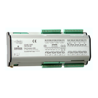
EC3-812 Dual Circuit Rack Controller
Operating Instructions
GB
Alarm Codes
HP General alarm HP
Controller 1 + 2: High pressure signal from digital input
LP General alarm LP
Controller 1 + 2: Low pressure signal from digital input
hP Limit violation suction side
Controller 1 + 2: Suction pressure higher than the maximum limit
lP Limit violation suction side
Controller 1 + 2: Suction pressure lower than the minimum limit
EP Sensor failure suction side
Controller 1: Suction pressure sensor 1 failure
Controller 2: Suction pressure sensor 2 failure
Ed Sensor failure condenser
Controller 1 + 2: Discharge pressure sensor failure
Fr Fast recovery suction low
Controller 1 + 2: Fast recovery from low suction pressure
hr Fast recovery condensing
Controller 1 + 2: High discharge pressure recovery
d1 Discharge temperature alarm 1
Controller 1: discharge end temperature associated with compressor B 1
is to high
d2 Discharge temperature alarm 2
Controller 1: discharge end temperature associated with compressor B 2
is to high
d3 Discharge temperature alarm 3
Controller 1: discharge end temperature associated with compressor B 3
is to high
E1 Feedback alarm 1
Controller 1: Digital input associated with compressor B1 has changed
into alarm state (safety chain)
Controller 2: Digital input associated with compressor A1 has changed
into alarm state (safety chain)
E2 Feedback alarm 2
Controller 1: Digital input associated with compressor B2 has changed
into alarm state (safety chain)
Controller 2: Digital input associated with compressor A2 has changed
into alarm state (safety chain)
E3 Feedback alarm 3
Controller 1: Digital input associated with compressor B3 has changed
into alarm state (safety chain)
Controller 2: Digital input associated with compressor A3 has changed
into alarm state (safety chain)
E4 Feedback alarm 4
Controller 2: Digital input associated with compressor A4 has changed
into alarm state (safety chain)
n1 Service alarm compressor 1
Controller 1: Compressor B1 operating time higher than run limit
Controller 2: Compressor A1 operating time higher than run limit
n2 Service alarm compressor 2
Controller 1: Compressor B2 operating time higher than run limit
Controller 2: Compressor A2 operating time higher than run limit
n3 Service alarm compressor 3
Controller 1: Compressor B3 operating time higher than run limit
Controller 2: Compressor A3 operating time higher than run limit
n4 Service alarm compressor 4
Controller 2: Compressor A4 operating time higher than run limit
oL Oil receiver level alarm
Controller 1: Oil level detection from digital input
rL Refrigerant level alarm
Controller 1: Refrigerant level detection from digital input
Er Data error - out of range
Data send to the display is out of range
Messages
--- No data
The display will show an “---” at node start up, when no data is send to
the display or when the display is disabled.
In Configuration data initialization
The display will show an “In” when the configuration data are
initialized with the factory default values.
Id Wink request received
The display will show a flashing “Id” when the wink request was
received. The node will receive the flashing “Id” will be shown on the
display until the service button will be pressed, or a 30 min delay timer
will expire or a second wink request.
oF Offline
The node is offline: no application is running. This is the result of a
network management command an will happen
- -- --- Controller disabled, waiting for restart
After a major change of the configuration parameter, the rack controller
1 and 2 are disabled for 20 seconds. After this delay the controllers
restart automatically.
The rack controller 1 and 2 are disabled (with object status or with the
network variable nviContEnable[0] and nviContEnable[1]).

 Loading...