Operating instructions
EXD-SH1/2 Controller with ModBus communication
capability for electrical control valves
Emerson Climate Technologies GmbH www.climate.emerson.com/en-gb Date: 29.07.2020
Am Borsigturm 31 I 13507 Berlin I Germany EXD-SH12_OI_EN_DE_FR_IT_PL_RU_0720_R04_865917.docx
General information:
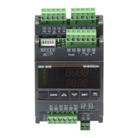
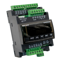
EXD-SH1/2 are stand-alone superheat and or temperature controllers. EXD-SH1 is
intended for operation of one bipolar electrical control valve whereas EXD-SH2 is
designed for operation of two independent bipolar electrical control valves.
A table of the available application possibilities is listed below:
Superheat or temperature control
Superheat or temperature control
Notes:
It is possible to use only circuit 1 from EXD-SH2. In this case, the circuit 2 must
be disabled (C2 parameter) and the sensors and the valve for the second circuit
are not needed.
ModBus communication is described in a Technical Bulletin and it is not
covered by this document.
Technical data:
24VAC/DC +10%/-10% 50/60HZ,
EXD-SH1: 25VA EXD-SH2: 50VA
Removable screw terminals wire size 0.14...1.5 mm
2
Temperature sensors
ECN-N… / TP1… (temperature range down to -45°C)
ECN-Z… (temperature range down to -
80°C ultra low
temperature)
operating/surrounding
0…+55°C
between EXD-SH and
50 cm
AWG 18 wire size (≥ 1mm
2
)
PT5N, PT5N-FLR or ratiometric probes
Output alarm relay current
rating
Resistive Load 24 V AC/DC, 1 A
Inductive Load 24 V AC/DC, 0.5 A
During normal operation and supply power OFF
Stepper motor output
Valves: EX4-8 (EX4-7-FLR)
CV4-7
Marking
,
Warning:
EXD-SH1/2 (EXD-PM, ECP-024) has a potential ignition source and does not
comply with ATEX requirements. Installation only in non-explosive
environment. For flammable refrigerants only use valves and accessories
approved for it!
Dimensions (mm):
Safety instructions:
• Read operating instructions thoroughly. Failure to comply can result in device
failure, system damage or personal injury.
• It is intended for use by persons having the appropriate knowledge and skill.
• Before installation or service disconnect all voltages from system and device.
• Do not operate system before all cable connections are completed.
• Do not apply voltage to the controller before completion of wiring.
• Entire electrical connections have to comply with local regulations.
• Inputs are not isolated, potential free contacts needed to be used.
• Disposal: Electrical and electronic waste must NOT be disposed of with other
commercial waste. Instead, it is the user responsibility to pass it to a
designated collection point for the safe recycling of Waste Electrical and
Electronic Equipment (WEEE directive 2012/19/EU). For further
information, contact your local environmental recycling center.
Temperature setting in normal sense
(Controller function as temperature controller)
Valve opening %
1tbd
100%
Temperature
0%
1tAL 1tst 1tAH
Temperature setting in reverse sense
(Controller function as temperature controller)
Valve opening %
1tbd
100%
Temperature
0%
1tAL 1tst/ 1tAH
Electrical connection and wiring:
• Refer to the electrical wiring diagram for electrical connections.
• Note: Keep controller and sensor wiring well separated from supply power
cables. Minimum recommended distance 30 mm.
• When connecting the wires of the EXV-M… (electrical plug of valves)
consider the color coding as follows:
EXV-M…: WH: White; BK: Black; BN: Brown; BL: Blue
• The digital input DI1 (EXD-SH1/SH2) and DI2 (EXD-SH2) are the interfaces
between EXD-SH1/2 and upper level system controller if the Modbus
communication has not been used. The external digital inputs must be free of
potential (dry contact) and shall be operated in function system’s
compressor/demand.
External contact to be closed (Start)
External contact to be open (Stop)
Note: Connecting any EXD-SH1/2 inputs to the supply voltage will permanently
damage the EXD-SH1/2
.