Instruction Manual
D200126X012
2502 Controllers
June 2017
10
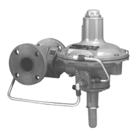
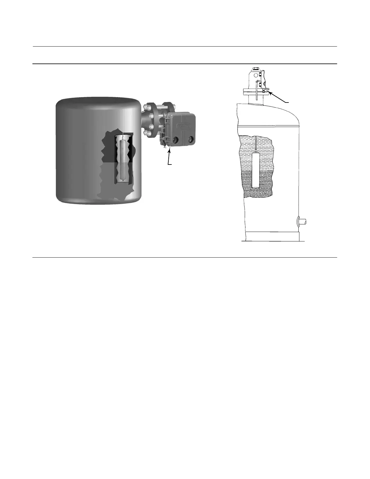
Figure 7. Cageless Sensor Mounting
CF5380‐A
A3893
TOP MOUNTED
SIDE VIEW (WITHOUT STILLWELL)
SIDE VIEW (SHOWING STILLWELL)
SIDE MOUNTED
W9517‐1
If an extension is used between the displacer spud and the displacer stem end piece, make sure the nuts are tight at
each end of the displacer stem extension. Install and tighten suitable bolting or cap screws in the flanged connection
to complete the installation.
Top‐Mounted Sensor
Figure 7 shows the installation of a top‐mounted cageless sensor. The displacer may be attached to the displacer rod
before installing the sensor on the vessel. Where the displacer diameter is small enough, it may be desirable to install a
long or sectionalized displacer through the sensor head access hole after the sensor is installed on the vessel. Connect
the displacer as shown in figure 8, locking the assembly with the cotter springs provided. If a stem is used between the
displacer as shown in figure 8, lock the assembly with the cotter springs provided. If a stem is used between the
displacer spud and the stem end piece, make sure the nuts are tight at each end of the stem. Install and tighten
suitable cap screws in the flanged connection to complete the installation.

 Loading...