Instruction Manual
D103292X012
C1 Controllers and Transmitters
March 2017
21
To better understand the adjustments and overall operation of the controller, refer to the Principle of Operation
section in this manual for differential gap controllers and the schematic diagram in figure 13.
Adjustments
Adjustment: Set Point
The position of the pressure setting knob determines the location of the differential gap within the range of the
pressure sensing element. Move the pointer to the desired pressure where the output of the controller should switch
from zero to full supply pressure with rising process pressure (direct-acting controllers) or with falling process pressure
(reverse-acting controllers).
Adjustment: Proportional Band
The proportional band adjustment shown in figure 4 determines the width of the differential gap. The width of the gap
is the difference between the process pressures at which the controller output will switch from zero to full supply
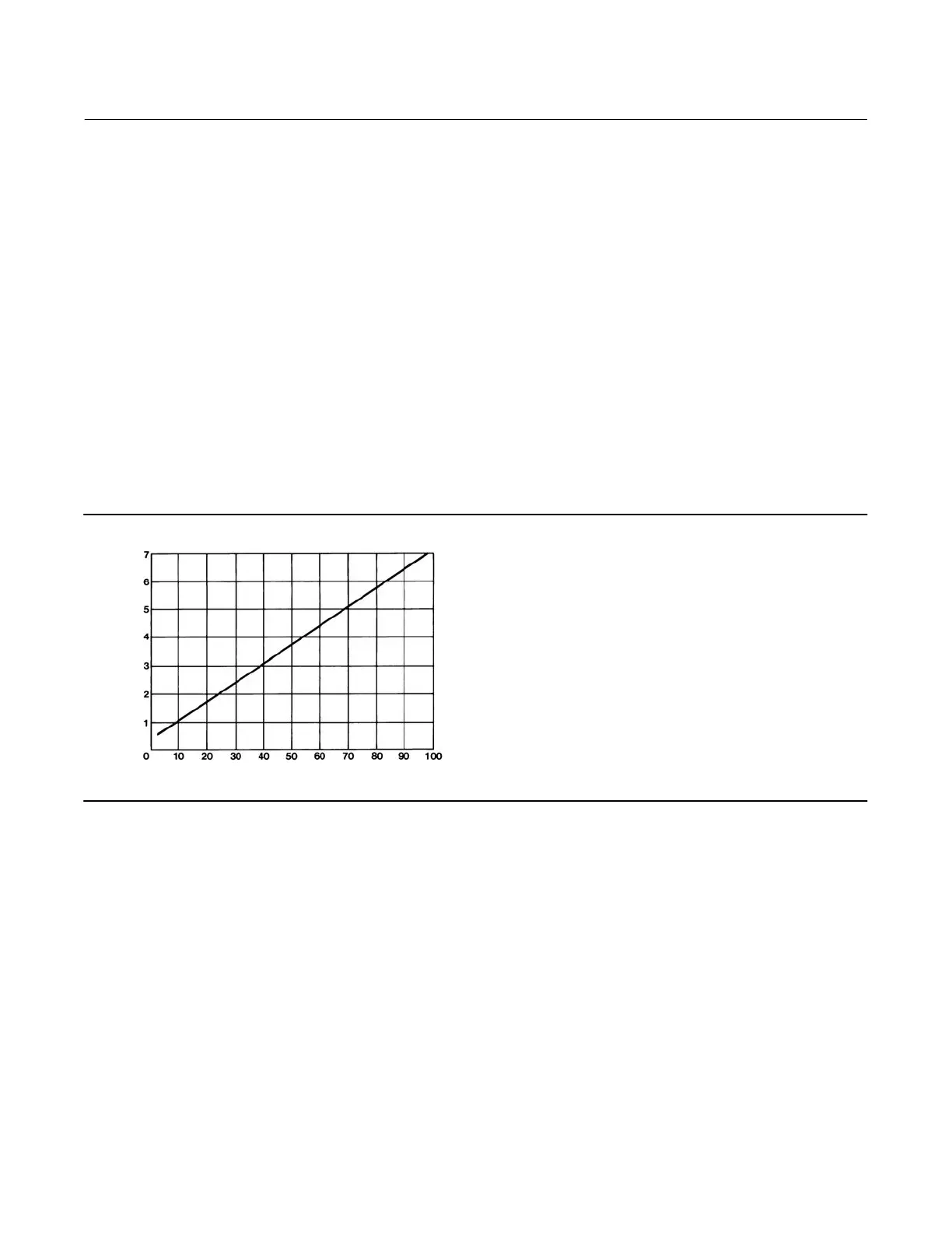
pressure, or from full supply pressure to zero. The relationship between the proportional band dial setting and the
differential gap is shown in figure 10.
Figure 10. Differential Gap Adjustment for Differential Gap Controllers
A2202-3
PROPORTIONAL BAND KNOB SETTING
DIFFERENTIAL GAP (PERCENT OF ELEMENT RANGE)
Calibration: Differential Gap Controllers
The output of each controller is checked at the factory before the unit is shipped. Before placing the controller in
control of a process loop, check to verify that the controller is calibrated correctly for the application. The controller
must be connected open loop (Open loop: The controller output pressure changes must be dead ended into a
pressure gauge).
1. Temporarily convert the differential gap controller to proportional-only controller by disconnecting the
proportional tubing (key 25, figure 16) from the mounting base. Reinstall the tubing into the other connection in
the mounting base. Remove the proportional band assembly and invert it as shown in figure 16. Do not invert the
reversing block (key 37, figure 16).
2. Temporarily invert the proportional band assembly (refer to figure 17):
a. Turn the proportional band assembly (key 73) to 10.
b. Unscrew the spring adjustor (key 65), removing the bias spring (key 70) and washers (key 62) with it.

 Loading...