Instruction Manual
D103292X012
C1 Controllers and Transmitters
March 2017
24
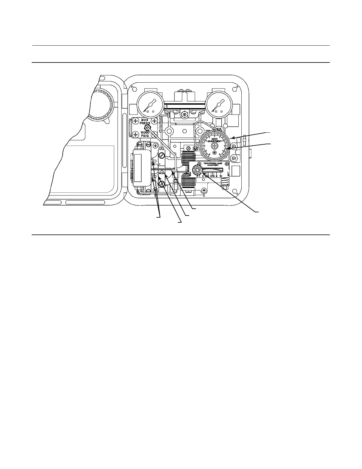
Figure 11. Transmitter Adjustment Locations
PRESSURE SETTING
DIAL (KEY 6)
ADJUSTER SCREWS (KEY 48)
CALIBRATION ADJUSTER (KEY 36)
FLAPPER (KEY 40)
NOZZLE (KEY 54)
SPAN ADJUSTMENT KNOB
ZERO ADJUSTMENT KNOB
(KEY 58)
GE34729-B
E1061
Adjustment: Span
The span adjustment is graduated from 0 to 10. A setting of 10 represents a span setting of 100 percent of the process
sensing element range. The transmitter achieves the highest accuracy when the span is 100 percent.
The transmitter span adjustment shown in figure 11 is the same as the controller proportional band adjustment.
Calibration: Transmitters
The output of each transmitter is checked at the factory before the unit is shipped. The transmitter provides an output
signal that is proportional to the pressure applied to the sensing element. The output pressure has no direct effect on
the process pressure.
The transmitter is calibrated at the factory and should not need additional adjustment. Use the following calibration
procedures when the sensing element has been changed or other maintenance procedures have altered the
calibration of the transmitter. The following procedures use a 0.2 to 1.0 bar (3 to 15 psig) output pressure range as an
example. For other output pressure ranges [such as 0.4 to 2.0 bar (6 to 30 psig)] adjust the values to match the
application.
 Loading...