Instruction Manual
D100399X012
EW Valve
July 2017
5
Check with your process or safety engineer for any additional measures that must be taken to protect against process
media.
If installing into an existing application, also refer to the WARNING at the beginning of the Maintenance section in this
instruction manual.
CAUTION
When ordered, the valve configuration and construction materials were selected to meet particular pressure, temperature,
pressure drop and controlled fluid conditions. Responsibility for the safety of process media and compatibility of valve
materials with process media rests solely with the purchaser and end‐user. Since some body/trim material combinations
are limited in their pressure drop and temperature ranges, do not apply any other conditions to the valve without first
contacting your Emerson sales office
or Local Business Partner.
Before installing the valve, inspect the valve and pipelines for any damage and any foreign material which may cause
product damage.
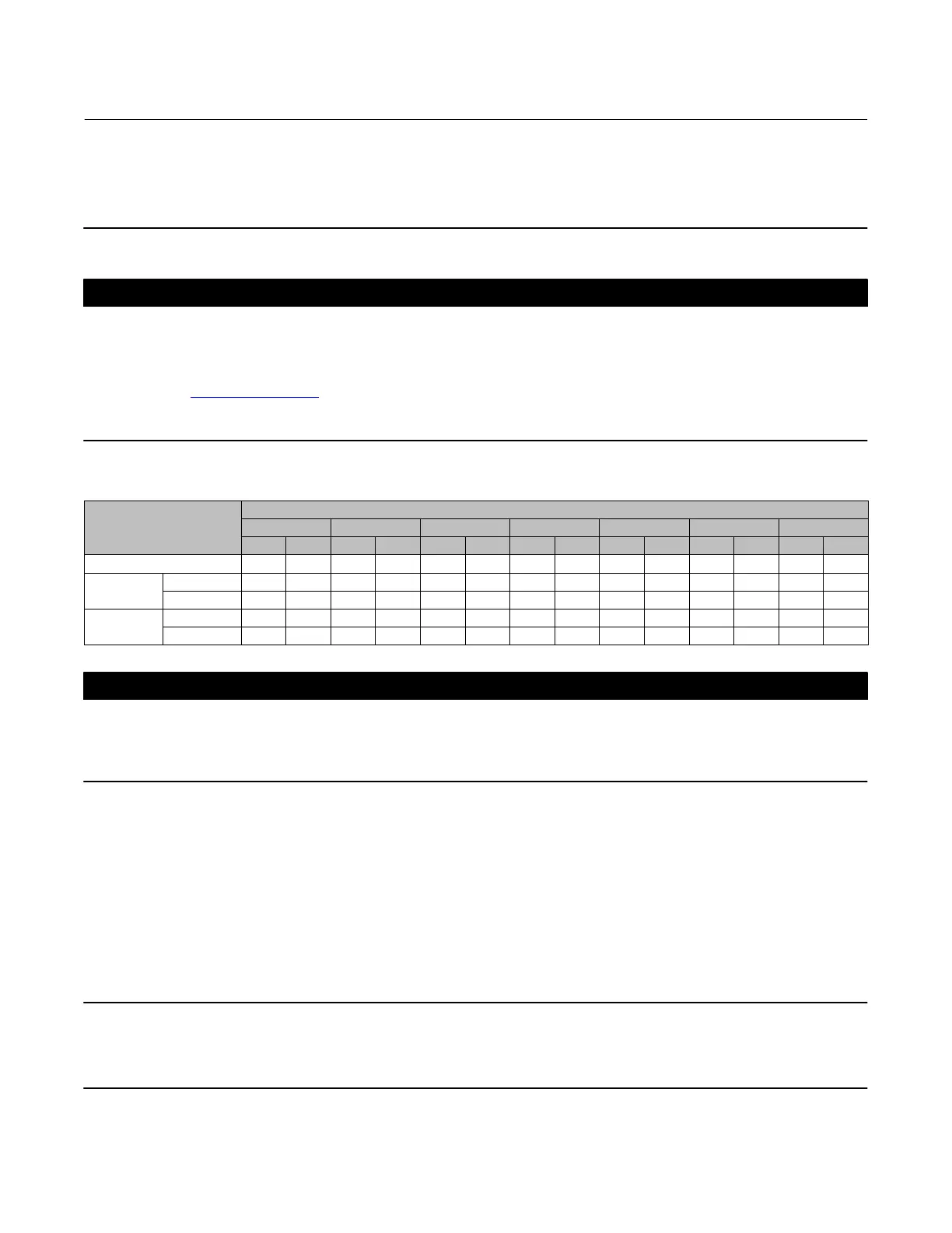
Table 4. Approximate Weights
END CONNECTION
VALVE SIZE, NPS
4X2 6X4 8X4 8X6 10X8 12X6 12X8
Kg Lb Kg Lb Kg Lb Kg Lb Kg Lb Kg Lb Kg Lb
CL300 (flanged only) 84 185 150 330 234 515 284 625 567 1250 500 1102 653 1440
CL600
Flanged 100 220 195 430 272 600 308 680 744 1640 721 1590 857 1890
Buttwelding 61 135 122 270 177 390 272 600 512 1130 526 1160 658 1450
CL900
Flanged ‐ ‐ ‐ ‐ ‐ ‐ ‐ ‐ ‐ ‐ ‐ ‐ ‐ ‐ ‐ ‐ ‐ ‐ 612 1350 ‐ ‐ ‐ ‐ ‐ ‐ ‐ ‐ ‐ ‐ ‐ ‐ 1361 3000
Buttwelding ‐ ‐ ‐ ‐ ‐ ‐ ‐ ‐ ‐ ‐ ‐ ‐ ‐ ‐ ‐ ‐ ‐ ‐ 454 1000 ‐ ‐ ‐ ‐ ‐ ‐ ‐ ‐ ‐ ‐ ‐ ‐ 1293 2850
CAUTION
If hoisting the valve, use a nylon sling to protect the surfaces. Carefully position the sling to prevent damage to the actuator
tubing and any accessories. Also, take care to prevent people from being injured in case the hoist or rigging slips
unexpectedly. Refer to table 4 for valve assembly weights. Be sure to use adequately sized hoists and chains or slings to
handle the valve.
1. Before installing the valve, inspect the valve body cavity and associated equipment for any damage and any foreign
material.
2. Make certain the valve body interior is clean, that pipelines are free of foreign material, and that the valve is
oriented so that pipeline flow is in the same direction as the arrow on the side of the valve.
3. Install the control valve assembly in any orientation unless limited by seismic criteria. However, the normal method
is with the actuator vertical above the valve. Other positions may result in uneven valve plug and cage wear and in
improper operation. With some valves, the actuator may also need to be supported when it is not vertical. For more
information, consult your Emerson sales office or Local Business Partner.
Note
If installing a valve with small internal flow passages, such as with WhisperFlo, Whisper Trim, or Cavitrol cages, consider installing
an upstream strainer to prevent the lodging of particles in these passages. This is especially important if the pipeline cannot be
thoroughly cleaned or if the flowing medium is not clean.
 Loading...