Quick Start Guide
D103556X012
DVC6200 Digital Valve Controllers
August 2015
19
Step 2—Connect the Pneumatic Tubing
NOTE:
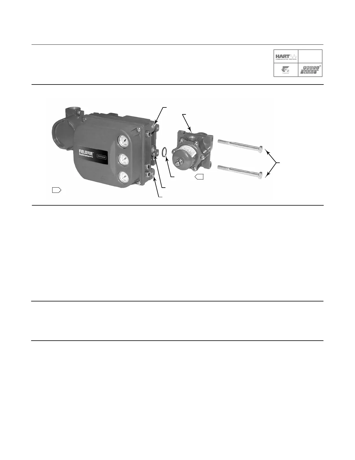
1 APPLY LUBRICANT
1
W9702-1
67CFR
CAP SCREWS
O‐RING
SUPPLY CONNECTION (1/4 NPT)
Figure 16. Integral Mounting of a Fisher 67CFR Regulator on a FIELDVUE DVC6200 Digital Valve Controller
OUTPUT A (1/4 NPT)
OUTPUT B (1/4 NPT)
1. Connect the DVC6200 pneumatic output to the actuator input using at least 10 mm (3/8inch) diameter tubing.
D When using a singleacting direct digital valve controller (relay A or C) on a singleacting actuator, connect
OUTPUT A to the actuator pneumatic input.
D When using a singleacting reverse digital valve controller (relay B) on a singleacting actuator, connect OUTPUT
B to the actuator diaphragm casing.
D When using a doubleacting digital valve controller (relay A) on a doubleacting actuator, connect OUTPUT A and
OUTPUT B to the appropriate actuator pneumatic input. With no input current to the DVC6200, OUTPUT A is at
zero pressure and OUTPUT B is at full supply pressure when the relay is properly adjusted.
Note
To have the actuator stem extend from the cylinder with increasing input signal, connect OUTPUT A to the actuator cylinder
connection farthest from the actuator stem. Connect OUTPUT B to the cylinder connection closest to the actuator stem. To have
the actuator stem retract into the cylinder with increasing input signal, connect OUTPUT A to the actuator cylinder connection
closest to the actuator stem. Connect OUTPUT B to the cylinder connection farthest from the actuator stem.
SIS

 Loading...


