Safety
Information
Product
information
Mechanical
Installation
Electrical
installation
Getting
started
Basic
parameters
Running the
motor
Optimization
SMARTCARD
operation
Onboard
PLC
Advanced
parameters
Technical
data
Diagnostics
UL
information
Mentor MP User Guide 25
Issue: 3 www.controltechniques.com
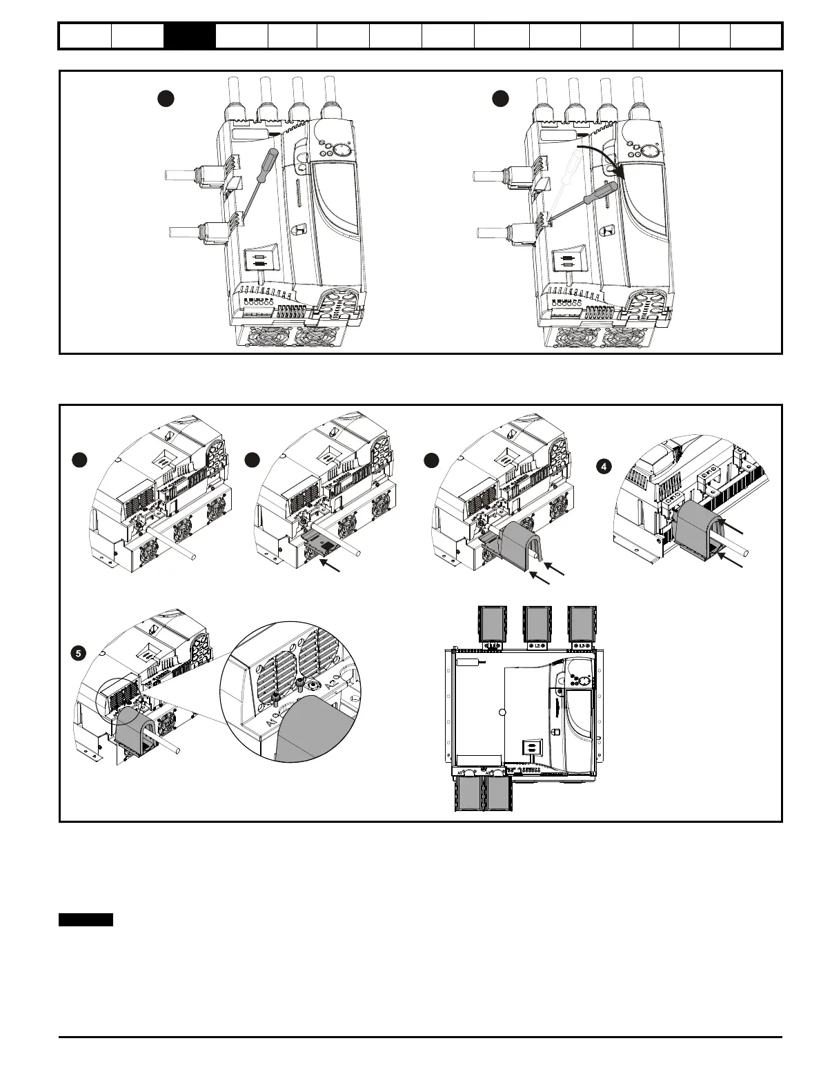
Figure 3-15 Removing the terminal shrouds on size 1 drives
1. Insert the screwdriver as shown.
2. Lever in the direction shown to unclip the terminal shroud and remove.
Figure 3-16 Installing the terminal shrouds on size 2 drives
1. Assemble the cable to the busbar.
2. Place the terminal shroud base cover underneath the cable in the orientation shown.
3. Place the terminal shroud over the cable in the orientation shown, slide the terminal shroud on to the base cover in the direction shown until it
clicks in to place.
4. For all power connections slide in the terminal shroud sub-assembly in the direction as shown.
5. Insert the 2 x M4 x 16 screws using a pozi drive screwdriver.
To remove the terminal shrouds, please reverse the process above.
 Loading...
