Sensi
™
Wi-Fi Programmable Thermostat Installation Guide 12
Notes
Sensi
Terminals
Single/Multi-Stage
Conventional System
Heat Pump System
RH*
RC*
C Common wire, 24V
Y 1st outdoor stage cooling 1st stage heat and cool
Y2 2nd outdoor stage cooling 2nd stage heat and cool
W/E 1st indoor stage heat 1st stage auxiliary/emergency heat
W2
2nd indoor stage heat 2nd stage auxiliary/emergency
heat
G Indoor blower (fan)
O/B Changeover (reversing valve) connection for heat pump or zone
panel systems
L No function “L” terminal connection
*Two transformer systems (separate RC and RH wires), clip internal jumper
located on back of Sensi above battery compartment.
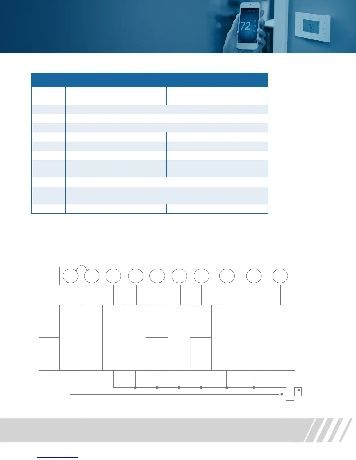
Terminal outputs
Terminal outputs and wiring diagrams
Single Stage or Multi-Stage System (No heat pump) with Single Transformer
Single Stage or Mul-Stage System (No Heat Pump) with Single Transformer
* Internal jumper between RC and R H, located on back of thermostat above battery compartment.
**Common connection required for Heat-only or Cool-only systems.
HOT
NEUTRAL
24 VAC
120 VAC
NEUTRAL
Single
stage
AC1
GA1
EL1
24 Volt
(Hot)
Cool
24 Volt
(Hot)
Heat
24 Volt
(Common)
Cool
Mode 1
st
stage
No
output
Heat
Mode 1
st
stage
No
output
Blower /
circulator fan
energized on
call for cool
(and heat if
configured
for electric
heat)
O
Energized
constantly
in Cool
Mode
B
Energized
constantly
in Heat
Mode (or
Aux Mode)
Heat Pump
“L” terminal
connection
Multi -
stage
AC2
GA2
EL2
Cool
Mode 2
nd
stage
Heat
Mode 2
nd
stage
Dots indicate
phase
relaonship.
 Loading...