Sensi
™
Wi-Fi Programmable Thermostat Installation Guide 13
Notes
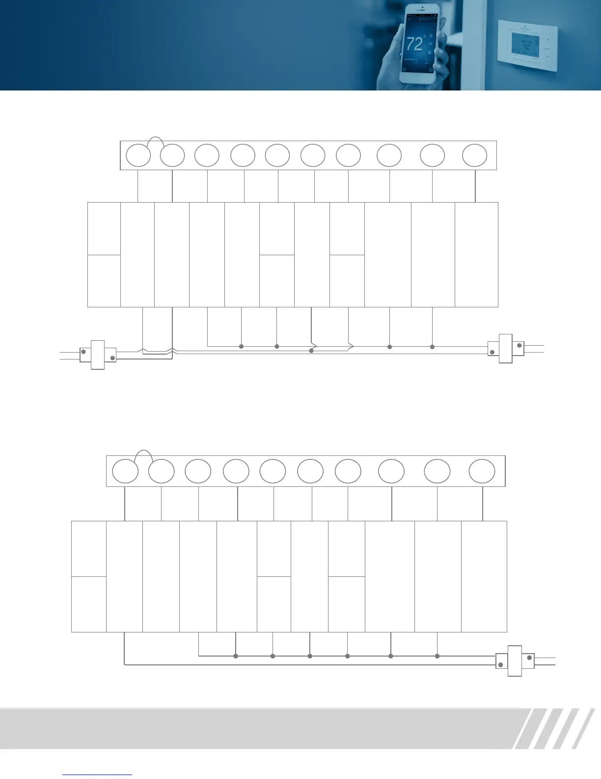
Single Stage or Mul-Stage System (No Heat Pump) with Two Transformers
*Two transformer systems (separate RC and RH wires), clip internal RC/RH jumper, located on back of thermostat above battery compartment.
Single
stage
AC1
GA1
EL1
24 Volt
(Hot)
Cool
24 Volt
(Hot)
Heat
24 Volt
(Common
Cool
Mode 1
st
stage
No
output
Heat
Mode 1
st
stage
No
output
Blower /
circulator fan
energized on
call for cool
(and heat if
configured
for electric
heat)
Energized
constantly
in Cool
Mode
B
Energized
constantly
in Heat
Mode (or
Heat Pump
“L” terminal
connection
Multi -
stage
AC2
GA2
EL2
Cool
Mode 2
nd
stage
Heat
Mode 2
nd
stage
Dots indicate
phased
relaonship.
Dots indicate
phased
relaonship.
* Internal jumper between RC and R H, located on back of thermostat above battery compartment.
* * Common connection required on Heat -only, Cool -only or Heat Pump systems.
HOT
120 VAC
NEUTRAL
Single
stage
Heat
Pump
HP1
24 Volt
(Hot)
Cool
24 Volt
(Hot)
Heat
24 Volt
(Common
Heat and
Cool
Mode 1
st
stage
(compres
-
sor)
NOTE: Du
Fuel option
de-energizes
Heat Mode
1
st
stage
No
output
Heat
Mode 1
st
stage
No
output
Blower /
circulator fan
energized on
call for cool
(and heat if
configured
for electric
heat)
O
Energized
constantly in
Cool Mode
(Factory
Default)
B
Energized
constantly in
Heat Mode
(or Aux
Mode)
Heat Pump
“L” terminal
connection
Multi
-
stage
Heat
Pump
HP2
Cool
Mode
2
nd
stage
Heat
Mode 2
nd
stage
Dots indicate
phase
relationship.
Single Stage or Multi-Stage System (No heat pump) with Two Transformers
Heat Pump Systems
 Loading...