A G-TRAC2
IOM-25 22 of 42 Mar 99 R7
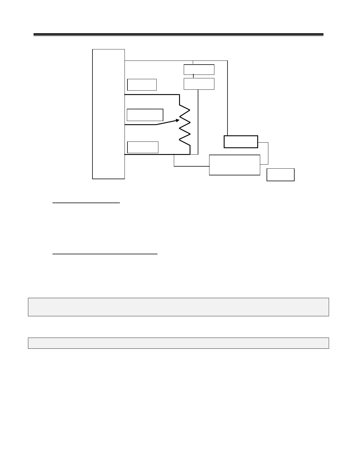
Multiple Room Sensors
Four sensors can be wired to give an average reading of room temperatures to the TRAC control. They must be wired in a
series/parallel arrangement. The drawing above drawing shows a circuit making use of the built in sensor in the TE6100
Johnson Sensor/Setpoint assembly and using TE6000 sensors for the other three. (The other three could also be TE6100, just
using the sensor wires.)
BMS Reset (Continuous blower only)
Dipswitch A-1 must be on to activate this option. This option requires an analogue voltage or current signal to be wired to
the optically isolated + and terminals. The analogue input signal proportionally increases the calculated discharge air set-
point. (The “calculated discharge set-point” equals the master discharge set point plus the input signal multiplied by a reset
ratio factor.)
NOTE: The direction of reset is up only. The maximum amount of reset is adjustable from 15ºF to 60ºF. The
maximum discharge temperature (dial set point plus reset) is limited to 120ºF.
The BMS reset option is activated by dipswitch A-1. Reset ratio pot is labelled “BMS Reset Pot”.
NOTE: As a standard, the G-TRAC2 is designed to operate with 4-20 ma or 2-10 VDC into a 500 OHM load.
Some BMS devices do not have enough drive (VA) to provide a full 10 VDC when connected to a 500-ohm load. The input
resistance for this operation can be increased to 1500-ohms by cutting resistor R48. (To cut this resistor you must turn the
board over. It is located on the back of the board, near the bottom, and close to the terminal ‘+’. This is a 1 watt 680 ohm
resistor; colors blue, grey, brown, gold.)
The BMS reset curve is not truly linear. Reset will usually be measurable at about 3 to 4 volts. The following sample table is
based on a minimum set point of 55°F with the maximum reset limit is set to 13ºC (or 24°F).
Built in TE6100
Sensor Element
 Loading...