EasyManua.ls Logo

Engineered air EngA G-TRAC2 User Manual

Engineered air EngA G-TRAC2
42 pages
To Next Page IconTo Next Page
To Previous Page IconTo Previous Page
Page #31 background image
A G-TRAC2
IOM-25 31 of 42 Mar 99 R7
Johnson Set-Point
4.1 Adjust DSP CAL until the SPC voltage reading matches the dial set point value divided by 10° will give VDC. Return
the dipswitches to their normal position.
Built In Set-Point
4.2 Loosen the setscrew on the set-point knob and move the knob until the dial set point agrees with the measured
set-point value. Tighten the setscrew and return the dipswitches to their normal position.
Room Sensor Calibration
1. Measure the room or return air temperature and set the room set-point dial to the measured value.
2. Record the settings of dipswitches 1, 2, and 3. Turn off dipswitches 1, 2, and 3.
3. Measure the G-TRAC2 calculated set point. (DC voltage from spade connector terminals “DTEMP” to “COMMON”.)
4. Turn dip switch 3 on.
5. Measure the G-TRAC2 calculated set point DC voltage again. Adjust the ROOM CAL pot until the “SPC” to “COMMON”
voltage is the same as was measured in step C.
6. Return the dipswitches to their normal position.
BMS Calibration and Set Up
Refer to notes for BMS (Section XVII, page 23).

Table of Contents

Question and Answer IconNeed help?

Do you have a question about the Engineered air EngA G-TRAC2 and is the answer not in the manual?

Engineered air EngA G-TRAC2 Specifications

General IconGeneral
BrandEngineered air
ModelEngA G-TRAC2
CategoryController
LanguageEnglish

Summary

Product Overview and System Basics

Application

Defines the unit's purpose in heating, vent, and MUA applications.

Service Information

Guidance on technician familiarity with the manual before servicing equipment.

General Description

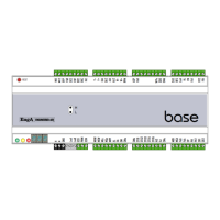
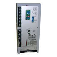
Overview of the G-TRAC2 as a programmed logic controller for heating.

Basic Features

Lists key operational and control capabilities of the G-TRAC2 unit.

System Configuration and Operation

System Timings

Details operational time sequences for pre-purge, warm-up, and cool-down cycles.

Blower Air and Gas Modulation

Explains how the G-TRAC2 manages flow rates for combustion air and gas.

Dip Switches

Covers configuration settings for A, B (Fuel/Air Curves), and C (Control Modes).

Status Lights and Operational Controls

Pots

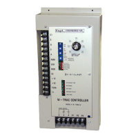
Lists and describes the 10 adjustable trim pots for various settings.

Status Lights

Explains LED indicators for operation modes and fault codes.

Burner Operation and Control Strategies

Auto Bypass Low Limit

Manages low-limit conditions with bypass timers and lockout prevention.

Day and Night Operating Strategies

Defines fan, damper, and heat control logic for day/night modes.

Basic Burner Operation and Related Settings

Basic Burner Operation Scheme

Outlines the sequence for burner start-up, ignition, and flame supervision.

BMS Reset and Calibration

Details using BMS signals for set point adjustment and calibration procedures.

Temperature Control and Setpoint Management

Temperature Control Overview

Describes discharge air control with optional resets and night heat packages.

Master Set-Point

Details using the unit's face-mounted set point or a remote thermostat.

Room Reset Thermostat Options

Explains how room temperature can adjust the discharge air set point.

Sensor Calibration and Setup

Discharge Temperature Readout

Method for measuring discharge temperature via voltage readings.

Discharge Sensor Calibration

Procedures for calibrating the discharge air temperature sensor.

Discharge Set-Point Calibration

Steps to calibrate the base discharge set point value.

Room Sensor Calibration

Process for calibrating the room temperature sensor input.

Burner Setup and Combustion Tuning

Burner Set Up

Rules for operator movement and manual service mode for burner adjustment.

Combustion Set Up

Step-by-step guide for setting gas and air operators for proper combustion.

Special Service Notes and Troubleshooting

Special Service Notes

Covers fuses, low limit lockouts, and solid-state contact issues.

Ignition Problems

Troubleshooting steps for issues with pilot ignition and flame sensing.

Water and Ice from Combustion

Addresses issues related to condensation within the unit.

Field Replacement and Miscellaneous

Replacing a G-TRAC2 in the Field

Guidance on replacing the control unit and re-checking combustion.

Changing Gas or Air Operator

Steps for replacing faulty gas or air operator motors.

Miscellaneous Notes

Final notes on flame relay, flue gas, and O2 checks.

Related product manuals