Manage the Cabling
A ) Use cable clips or tie wraps to attach the
cable to the racking. The cable must be
supported at least every 1.8 m (6 feet).
B ) Dress any excess cabling in loops so
that it does not contact the roof. Do not
form loops smaller than 12 cm (4.75
inches) in diameter.
Create an Installation Map
Create a paper installation map to record microinverter serial numbers
and position in the array.
A ) Peel the removable serial number label from each microinverter
and afx it to the respective location on the paper installation map.
B ) Peel the label from the IQ Envoy and afx it to the installation map.
C ) Always keep a copy of the installation map for your records.
Mount the Microinverters
A ) If the Enphase DC bulkhead connectors are not already attached to
the microinverters, attach them now. Make sure they are fully seated.
B ) Mount the microinverter bracket side up (as shown) and under the
PV module, away from rain and sun. Allow a minimum of 1.9 cm
(0.75 inches) between the roof and the microinverter. Also allow 1.3
cm (0.50 inches) between the back of the PV module and the top of
the microinverter.
C ) Torque the mounting fasteners (1/4-inch or 5/16-inch) as follows.
Do not over torque.
•
6 mm (1/4 inches) mounting hardware: 5 N m (45 to 50 in-lbs)
•
8 mm (5/16 inches) mounting hardware: 9 N m (80 to 85 in-lbs)
•
When using UL 2703 mounting hardware, use the manufacturer’s
recommended torque value
3
6
5
4
INSTALLATION
Position the Enphase Q Cable
A ) Plan each cable segment to allow connectors on the Enphase Q Cable
to align with each PV module. Allow extra length for slack, cable turns,
and any obstructions.
B ) Mark the approximate centers of each PV module on the PV racking.
C ) Lay out the cabling along the installed racking for the AC branch circuit.
D ) Cut each segment of cable to meet your planned needs.
1
Position the Junction Box
A ) Verify that AC voltage at the site is within range:
Service Type and Voltage: L1 - L2
240 V Split-Phase 211 to 264 VAC
208 V Single Phase 183 to 229 VAC
B ) Install a junction box at a suitable location on the racking.
C ) Provide an AC connection from the junction box back to the electricity
network connection using equipment and practices as required by local
jurisdictions.
2
Afx serial number labels
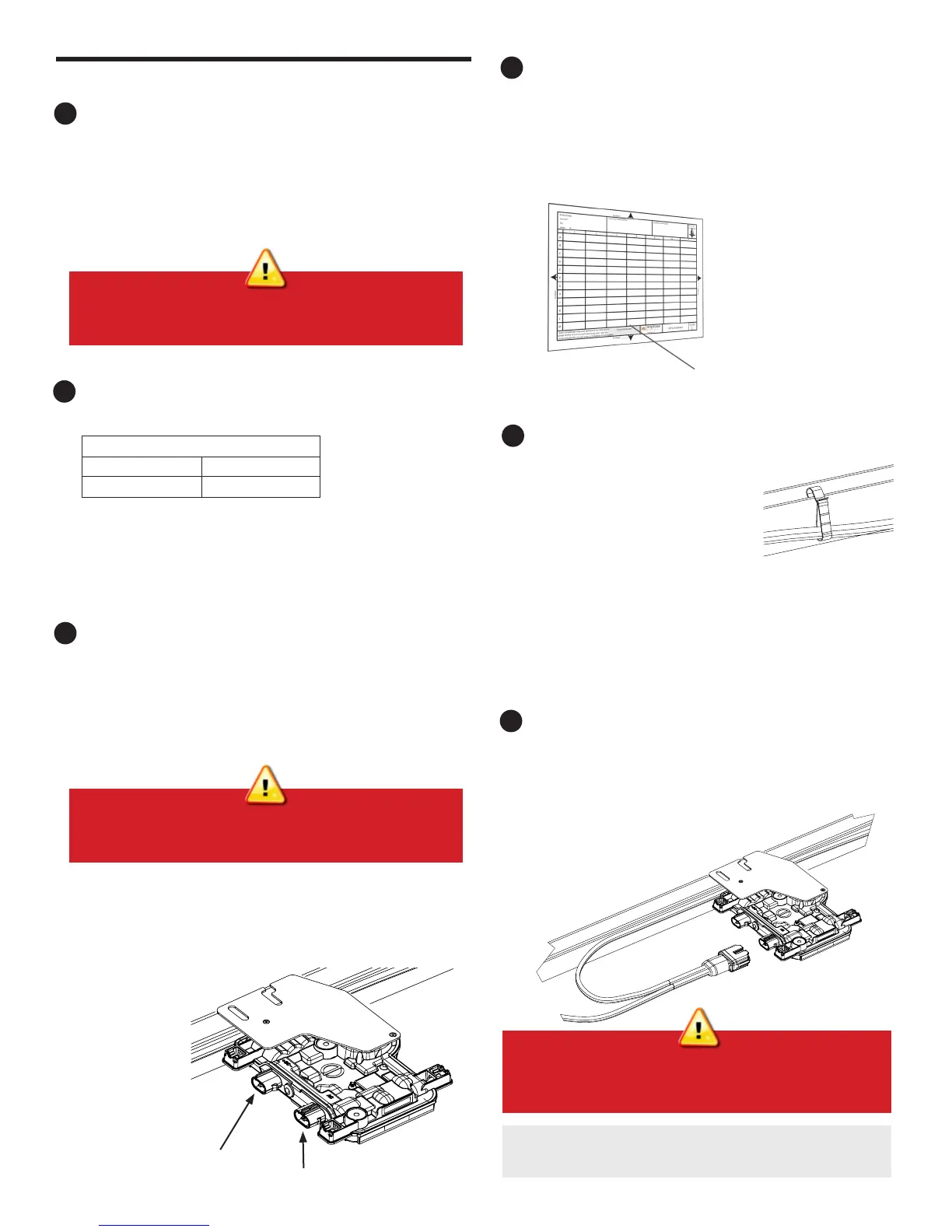
Connect the Microinverters
A ) Connect the microinverter. Listen for a click as the connectors
engage.
B ) Cover any unused connectors on the AC cable with Enphase
Sealing Caps. Listen for a click as the sealing caps engage.
To remove a sealing cap or AC connector, you must use an Enphase
disconnect tool.
Cable clip
WARNING: Install sealing caps on all unused AC connectors as
these connectors become live when the system is energized.
Sealing caps are required for protection against moisture ingress.
WARNING: When transitioning between rows, secure the cable to
the rail to prevent cable or connector damage. Do not count on the
connector to withstand tension.
DC connector
AC connector
WARNING: Install the microinverter under the PV module to avoid
direct exposure to rain, UV, and other harmful weather events. Do
not mount the microinverter upside down.
 Loading...


