A )
Make sure that the main load center wires are de-energized until you
have secured the CT wires in the terminal blocks.
B )
Before running the CT wires through the conduit, use colored tape to
mark one of the CTs and the free end of its wires.
C )
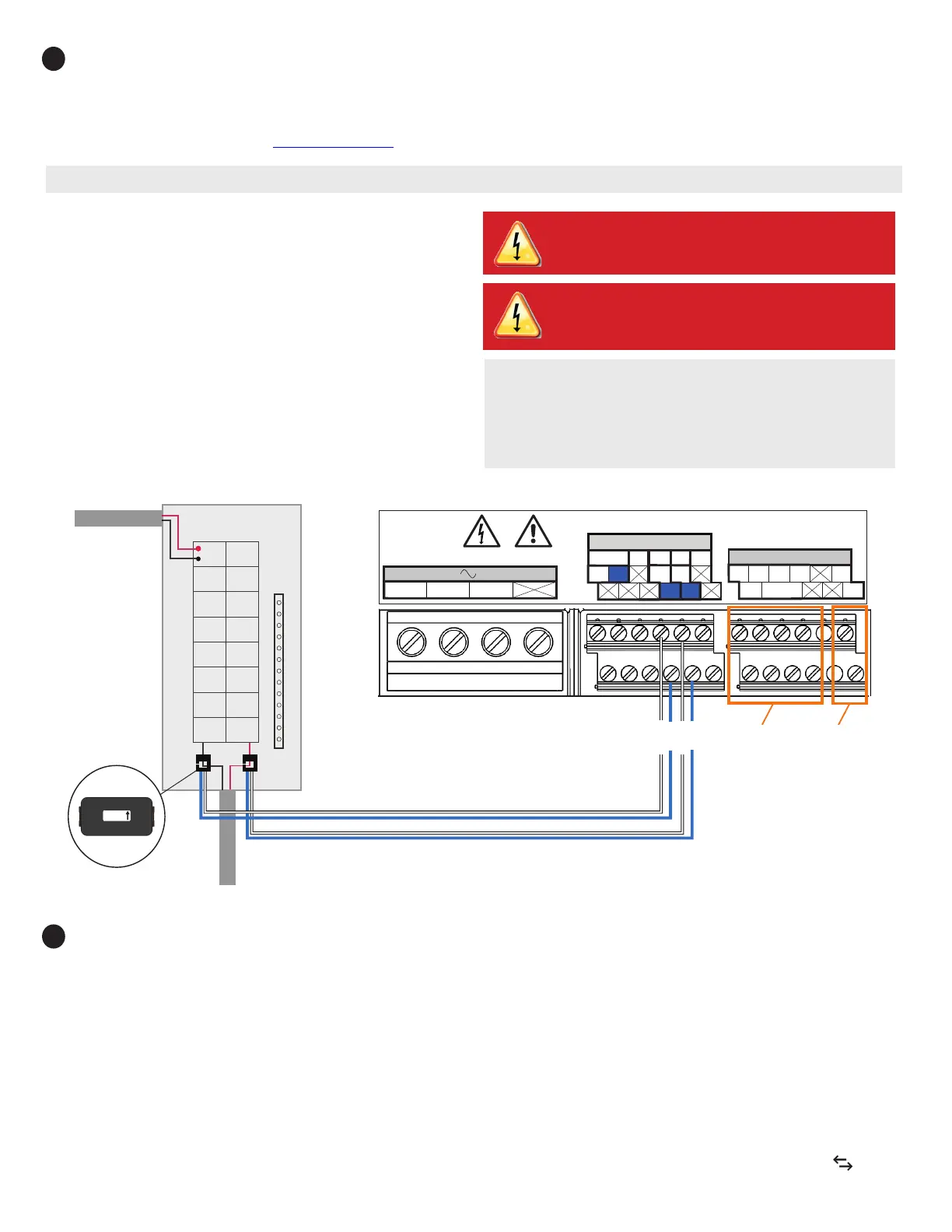
For the marked CT wires, connect the white and blue wires to the white
and blue “C1” terminals.
D )
For the unmarked CT wires, connect the white and blue wires to the
white and blue “C2” terminals.
E )
Tighten all connections to 5 in-lbs.
F )
Clamp the marked CT on the load center feed wire Line 1 (matching the
Envoy’s “L1” voltage terminal) with the CT arrow pointing toward the
load (away from the grid).
G )
Clamp the unmarked CT on the load center feed wire Line 2 (matching
the Envoy’s “L2” voltage terminal) with the CT arrow pointing toward
the load (away from the grid).
Install CTs for Consumption Metering (optional)
The IQ Envoy printed circuit board inside the IQ Combiner 3 is pre-wired at the terminal blocks for power and production metering connections. One solid-core cur-
rent transformer (CT) is provided for revenue grade production metering. You can install two optional split-core CTs to provide consumption metering. To do this,
you must create a protected route using conduit for the CT wires from the main load center to the IQ Envoy. If you need to extend the wires, refer to the Enphase IQ
Envoy Installation and Operation Manual at: enphase.com/support.
Notes: It is important to match CT and sense voltage phases. To proper-
ly measure power and energy, CT inputs must align with the respective
voltage inputs. Be sure to consistently identify and match the two AC
lines at two points: the main load center feed and the Envoy. Wire colors
(typically black and red) may not always consistently identify Lines 1
and 2. If in doubt, use a multimeter to check.
6
Note: Because of variance in load center design and main power feed, there may not always be enough space to install consumption metering CTs.
DANGER! Risk of electrocution! Do not install CTs when cur-
rent is owing in the sensed circuit. Always install CT wires
in the terminal blocks before energizing the sensed circuit.
Load Center
From IQ Combiner
IQ Envoy Terminal Block
Relay contacts
(if needed)
UP TO 250 Vac.
100A 0.5V 45-66Hz
white
blue
Not used
white
blue
P1 C1 C2
1 2 3 4
NO
Ref
Common
C
Digital Input Relay
PD, B300
OVC II
L1 L2
N
CU, 75C, 14AWG MIN
MEAS CAT III
OVC III
Production | Consumption
Consumption CTs
The arrows must point
toward the load — away
from the grid.
DANGER! Risk of electric shock. Always de-energize the load
center before beginning wiring.
Energize and Update the IQ Envoy
A ) Re-install the plastic deadfront. Start all of the screws, but do not
completely tighten them.
B ) Once all screws are partially tightened, go back and tighten each one
completely.
C ) Turn off the DG breaker(s).
D ) Reinstall the IQ Combiner 3 door.
E ) Turn on the circuit feeding the combiner.
F ) On the IQ Envoy (inside the Combiner), if the AP Mode LED is not lit,
press the AP Mode button.
G ) On your mobile device, go to Settings and join the Wi-Fi network “Envoy_
nnnnnn” (where “nnnnnn” equals the nal six digits of the Envoy serial
number).
H ) The app informs you if the software on the Envoy is not the latest version
by displaying the Envoy Software Update message. If the app displays
this message, follow the on-screen instructions to update the Envoy.
I ) For a short period (5-10 minutes), you must keep your mobile device
near the Combiner. Follow the on-screen instructions while the update
takes place.
The update may take up to 20 minutes. The Envoy reboots several times
during the update and the LEDs light up in varied sequences until the update
is complete.
Once the update is nished and the PV system is installed, the Envoy is
ready for Installation Part 2.
All four LEDs ash amber during boot up (approximately 3 minutes).
When boot up is complete, the Device Communications LED lights
solid amber, indicating that devices are not yet detected.
7
 Loading...


