IQ8MC/IQ8AC/IQ8HC Microinverters Installation and Operation Manual
17 © 2023 Enphase Energy Inc. All rights reserved. October 2023
USM-00008-1.0
Step 1: Position the IQ Cable
A. Plan each cable segment to allow drop connectors on the IQ Cable to align with each PV module. Allow extra
length for slack, cable turns, and any obstructions.
B. Mark the approximate centers of each PV module on the PV racking.
C. Lay out the cabling along the installed racking for the AC branch circuit.
D. Cut each segment of cable to meet your planned needs.
WARNING: When transitioning between rows, secure the cable to the rail to prevent cable damage or
connector damage. Do not count on the connector to withstand the tension.
Step 2: Position the junction box
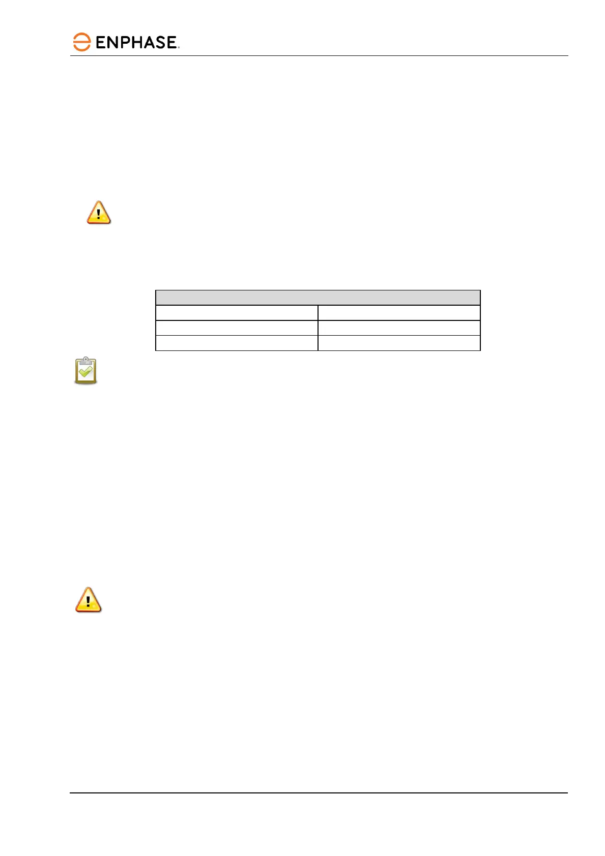
A. Verify that the AC voltage at the site is within range.
NOTE: For all installations, use the IQ Gateway to commission the microinverters to propagate correct grid
profile settings. This also ensures the microinverter’s firmware is upgraded whenever a newer version is
available.
*
In Mexico, only IQ8HC supports a 220 V grid.
B. Install a junction box at a suitable location on the racking.
C. Provide an AC connection from the junction box back to the electricity network using equipment and
practices as required by local jurisdictions.
Step 3: Mount the microinverters
A. The microinverters should be mounted beneath the modules either horizontally bracketed side up or vertically
and must be protected from direct exposure to rain, UV, and other harmful weather events. Please refer to the
image below for clearance requirements during vertical mounting.
• Allow a minimum of 1.9 cm (3/4 in) between the roof and the microinverter. Also, allow 1.3 cm (1/2 in)
between the back of the PV module and the top of the microinverter.
• For vertical mount, maintain >30 cm (12 in) clearance from the edges of the PV module to protect the
microinverter from direct exposure to rain, UV, and other harmful weather events.
WARNING: Install the microinverter under the PV module to avoid direct exposure to rain, UV, and other
harmful weather events. Do not mount the microinverter upside down.
B. Torque the microinverter fasteners as follows. Do not over-torque.
• 6 mm (¼ in) mounting hardware: 5 N m (45 in-lbs. to 50 in-lbs.)
• 8 mm (5/16 in) mounting hardware: 9 N m (80 in-lbs. to 85 in-lbs.)
• When using UL 2703 mounting hardware, use the manufacturer’s recommended torque value.
Horizontal mount
Service type and voltage: L1-L2
240 VAC Split-phase 211 to 264 VAC
208 VAC Single-phase 183 to 229 VAC
220 VAC Single-phase* 198 to 264 VAC
 Loading...