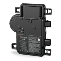
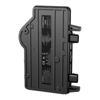
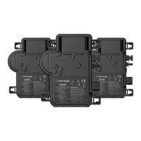
IQ8MC/IQ8AC/IQ8HC Microinverters Installation and Operation Manual
30 © 2023 Enphase Energy Inc. All rights reserved. October 2023
USM-00008-1.0
Connector spacing options
IQ Cable is available in three connector spacing options. The gap between connectors on the cable can be 1.3 meters,
2.0 meters, or 2.3 meters. The 1.3 meter spacing is best suited for connecting PV modules installed in portrait
orientation, while the 2.0 meter and 2.3 meter are for landscape orientation.
IQ Cable options
The cabling system is flexible enough to adapt to almost any solar design. To determine the cable type you need,
apply the following considerations:
• When mixing PV modules in both portrait and landscape orientation, you may need to transition between
cable types. See the preceding table for available cable types.
• To transition between cable types, install a Field Wireable Connector pair.
• In situations where portrait modules are widely spaced, you may need to use landscape-spaced cables for
the portrait-oriented PV modules and create loops of excess cable, if needed.
WARNING: Do not form loops smaller than 12 cm (4.75 in) in diameter.
Enphase IQ Cable accessories
The IQ Cable is available with several accessory options for ease of installation, including:
• Field Wireable Connectors (male) (Q-CONN-10M): Make connections from any field wireable female connector.
• Field Wireable Connectors (female) (Q-CONN-10F): Make connections from any IQ Cable open connector or Field
Wireable male connector.
• IQ Cable Clips (Q-CLIP-100): To fasten cabling to the racking or to secure looped cabling.
• IQ Disconnect Tool (Q-DISC-10): Disconnect Tool for IQ Cable connectors, DC connectors, and AC module mount.
• IQ Cable Sealing Cap (female) (Q-SEAL-10): One needed to cover each unused connector on the cabling.
• IQ Terminator (Q-TERM-10): One for each AC cable segment end; typically, two are needed per branch circuit.
Technical considerations
When installing the Enphase IQ8 Series Microinverter System
, consider the following factors.
WARNING: Risk of equipment damage. You must match the DC operating voltage range of the PV
module with the allowable input voltage range of the Enphase microinverter.
WARNING: Risk of equipment damage. The maximum open circuit voltage of the PV module
must not exceed the specified maximum input voltage of the Enphase microinverter.
• PV modules must have conductors labeled “PV Wire” or “PV Cable” to comply with NEC for ungrounded PV
power systems.
• Verify that the voltage and current specifications of the PV module match those of the
microinverter.
• The maximum short circuit current rating of the PV module must be equal to or less than the maximum
input DC short circuit current rating of the microinverter.
Cable Model Connector spacing PV module orientation Connector count per box
Q-12-10-240 1.3 m (50 in) Portrait 240
Q-12-17-240 2.0 m (78 in) Landscape (60-cell) 240
Q-12-20-200 2.3 m (90 in) Landscape (72-cell) 200
 Loading...
