INSTALLATION – SETUP AND OPTIONS
INPUT SELECTION
CAUTION:
Only change switch positions when the amplier is turned off.
CONTROL OUTPUT
The 1/8” (tip positive) 12-volt DC output jack can be used to turn on most components equipped with a 12-volt DC
input trigger. Voltage is delivered to the output jack when the amplier is “active”, or on. When the amplier turns off,
the voltage will drop to zero. Remember there is a delay of approximately fteen minutes before the amplier goes to
standby when using the Auto turn-on mode. Before connecting another device to the 12-volt output, please make sure
that the item’s trigger input is compatible with 12-volt DC and that it draws no more than 500mA.
POWER CONNECTION
Plug the power cord supplied with the amplier into the amplier and a 120V 60 Hz polarized wall outlet or appropriate surge
protector.
CAUTION:
DO NOT plug the amplier’s power cord into a switched outlet, such as what is provided on some Surround
Receivers. If you wish to have the amplier turn on when the Receiver is powered up, use one of the power modes, such
as Trigger or Audio.
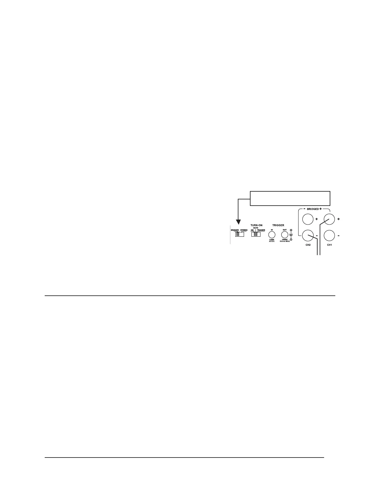
BRIDGING CHANNELS
For situations where two channels need to be combined into one, the
amplier can be bridged. Bridging combines the two input channels into
one more powerful mono output. To bridge channels on the E-2100, rst
make sure the power is off and switch the “stereo to bridged” switch into
the bridged position. Once in the bridged mode, connect your speaker
wire to the correct bridged position as labeled. Do not connect more than
one speaker to the bridged output without impedance protection devices.
The bridged output is 8 OHM. Do not connect speakers impedances
lower than 8 OHM to the E-2100 in bridged mode. Note: CH1 (+) Red and
CH2 (-) Black are your bridged speaker connections. Observe correct
polarity when bridging channels on the E-2100.
OPERATION
POWER SWITCH
The power switch on the front panel of the amplier will turn off the amplier no matter which power mode has been
selected. Refer to the “Power Mode” section for further information.
LED INDICATORS
When lit, the LED section on the front panel indicates that the amplier is operating. Each channel has one bi-color
LED assigned to it. Operation is normal when the LED is blue. A red LED indicates a short in the speaker wires
connected to that channel or a thermal issue that has the amplier in a temperature range that is too high.
LEVEL ADJUSTMENT
The level adjustments on the back panel of the amplier can be used to easily adjust the output level of the amplier
whether in stereo or bridged mode.
LOW PASS FILTER ADJUSTMENT
When enabled, the Low Pass Filter Adjustment allows the amplier to be used with passive subwoofers such as those
commonly installed in ceilings, walls and oors. The control can be used in either stereo or bridged mode and is variable
from 50Hz to 150Hz.
7
Wires to Speaker
(
+
)(–)
Observe correct connection and
polarity when bridging channels.
Switch to Bridged Mode
 Loading...