L200/L201/L100/L101 Revision A
Disassembly/Assembly Routing FFCs/cables 31
Confidential
1.4 Routing FFCs/cables
Scanner Unit /CIS (L200/L201)
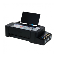
When routing the Panel FFC, route it through the ribs (x7) of the Housing, and secure with double-sided tape (x3).
When routing the Scanner FFC, secure it together with the Ferrite Core on the Housing with double-sided tape.
When routing the Scanner Motor cable, pay attention to the following instructions.
• Secure the Ferrite core with the hooks (x2) on the rear of the Scanner Unit.
• Route the Scanner Motor cable through the ribs (x2) and hook (x1) on the rear of the Scanner Unit, and through the hole of the section A and make one
turn around the frame of the section A.
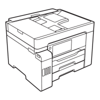
CR Motor
Route the CR Motor cable through the ribs (x10) and make one turn around the rib A.
Route the CR Motor cable so as not to touch the surrounding gears.
Main Board
Connect the following cable to the Main Board as shown in the figure above.
• PF Motor cable
• Power Supply Unit cable
• PF Encoder FFC
• CR Motor cable
• Head FFC
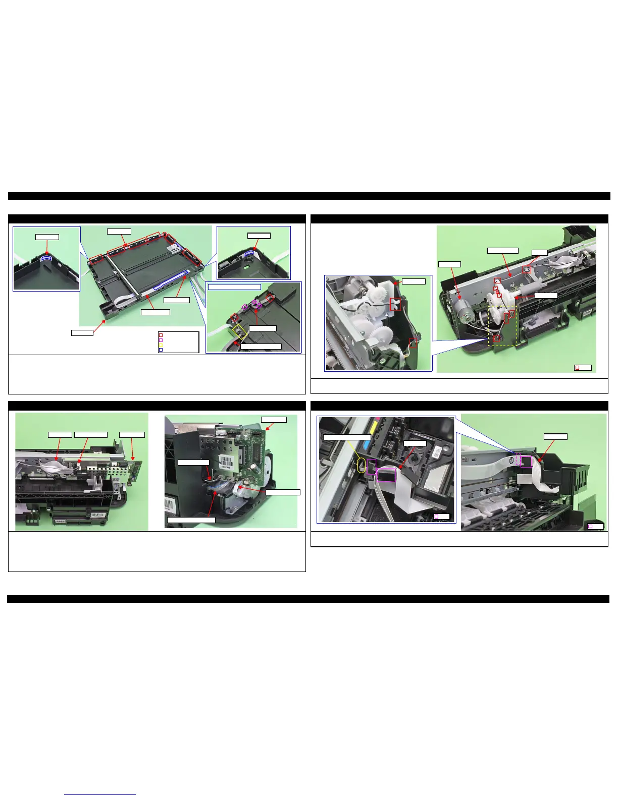
Printhead / Carriage
Confirm the CR Encoder Head FFC is surely connected.
Route the Head FFC through the rib of the Carriage as shown above.
 Loading...