L200/L201/L100/L101 Revision A
Adjustment Required Adjustments 34
Confidential
2.1 Required Adjustments
The table below lists the required adjustments depending upon the parts being repaired or replaced. Find the part(s) you removed
or replaced, and check which adjustment(s) must be carried out.
Note: <Meaning of the marks in the table>
“O” indicates that the adjustment must be carried out. “O
*
” indicates that the adjustment is recommended. “---” indicates that the adjustment is not required. If you have
removed or replaced multiple parts, make sure to check the required adjustments for the all parts. And when multiple adjustments must be carried out, be sure to carry out
them in the order given in the “Priority” row.
When the EEPROM Data Copy cannot be made for the Main Board that needs to be replaced, the Waste
Ink Tray Assy must be replaced after replacing the Main Board with a new one.
After all required adjustments are completed, use the “Final check pattern print” function to print all
adjustment patterns for final check. If you find a problem with the printout patterns, carry out the
adjustment again.
When using a new Main Board for replacing the Printer Mechanism, the Initial setting must have been
made to the Main Board.
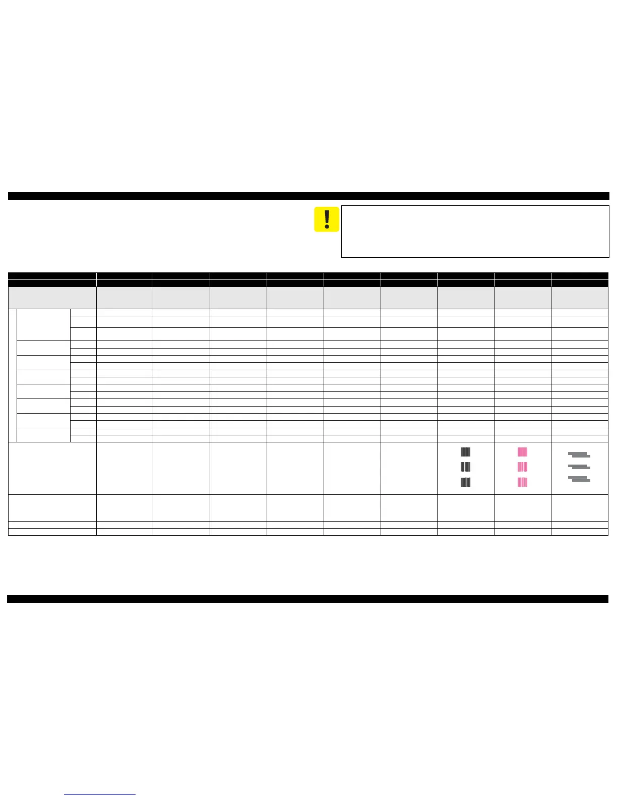
Table 2-1. Required Adjustment List
Priority 1 2 3 4 5 6 7 8 9
Adjustment Item EEPROM data copy Initial setting Maintenance counter reset Ink charge Head ID input Top margin adjustment Head angular adjustment Bi-D adjustment PF band adjustment
Purpose
To copy adjustment values or the
like stored on the old Main Board
to the new board when the Main
Board needs to be replaced.
To apply settings for the target
market after replacing the Main
Board.
To reset the waste ink counter /
the ink tube counter after
replacing the Waste Ink Pad / the
Tube Assy.
To fill ink inside the new
Printhead to make it ready for
print after replacing the
Printhead.
To correct characteristic
variation of the replaced
printhead by entering its
Printhead ID (Head ID).
To correct top margin of
printout.
To correct tilt of the Printhead
caused at the installation by
software.
To correct print start timing in bi-
directional printing by software.
To correct variations in paper
feed accuracy in order to achieve
higher print quality in band
printing.
Part Name
Main board
Remove
--- --- --- --- --- O O O O
Replace
(Read OK)
O --- --- --- --- --- --- --- ---
Replace
(Read NG)
--- O
O
(Replace the pad)
---OOOOO
Printhead
Remove
--- --- --- --- --- O O O O
Replace
--- --- --- O O O O O O
Power Supply Unit
Remove
--- --- --- --- --- O O O O
Replace
--- --- --- --- --- O O O O
LD Roller Assy
Remove
--- --- --- --- --- O O O O
Replace
--- --- --- --- --- O O O O
CR Motor
Remove
--- --- --- --- --- O O O O
Replace
--- --- --- --- --- O O O O
EJ Roller
Remove
--- --- --- --- --- O O O O
Replace
--- --- --- --- --- O O O O
Main Frame
Remove
--- --- --- --- --- O O O O
Replace
--- --- --- --- --- O O O O
Carriage Assy
Remove
--- --- --- --- --- O O O O
Replace
--- --- --- --- --- O O O O
Printout pattern
--- --- --- --- ---
See Figure 2-1.
How to judge
--- --- --- --- ---
Check if the top edge of the
paper is within -3 to +3 steps
from the standard line.
See “ 2.2 Details of Adjustments
(p36)” for the details.
Examine the printout patterns for
each of the four modes, and enter
the value for the pattern with no
gap and overlap for each mode.
Examine the printout patterns for
each of the four modes, and enter
the value for the pattern with no
gap and overlap for each mode.
Examine the printout patterns
and enter the value for the pattern
with no overlap and gap between
the two rectangles.
Adjustment program
OOOOOOOOO
Tool
--- --- --- --- --- --- --- --- ---
OK
NG
NG
OK
NG
NG
OK
NG
NG
 Loading...