Confidential
Disassembly/Reassembly Overview 20
M200 / M205 / M100 / M105 Series
Revision A
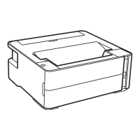
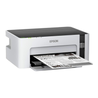
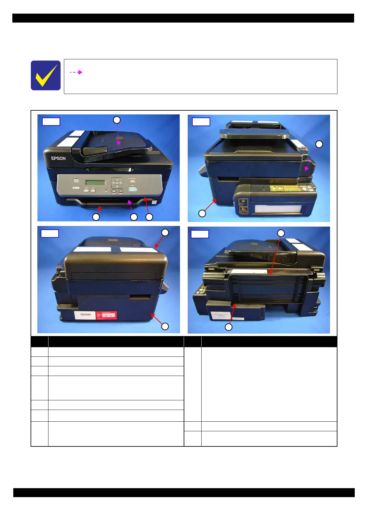
2.1.3 Locations of the Parts/Units
This section shows the locations of the main parts/units of this product.
Exterior parts
Figure 2-2. Exterior Parts
The parts/units which can not be seen in the following pictures are indicated in dotted lines
().
No. Name No. Name
1 Housing Rear (p34)
8
ADF/Scanner Unit (p34) (M200/M205 Series)
• ADF Unit (p42)
ADF Paper Guide Cover Assy (p35) / Paper Support
Cover (p35) / Bevel Gear Shaft (p42) / Combination
Gear 24.9.6 (p42) / ADF Document Support (p42) /
ADF Pad Assy (p42)
• Scanner Unit (p42)
Scanner Housing Upper (p42) / Scanner Carriage Unit
(p42) / Scanner Housing Lower (p42) / CIS Module
Unit (p42) / Scanner Motor (p42)
2 Tray Front Assy (p34)
3 Frame Base Assy (p41)
4
Panel Unit (p37)
Panel Board (p43) / Panel Button (p43) / Panel
Housing Upper Assy (p43)
5 Hinge (p34) (M200/M205 Series)
6 Housing Right (p34)
7
Housing Left Assy (p34)
• Housing Left (p43)
• Ethernet Cover (p43) (M200/M100 Series)
9 Paper Support (p34)
10 Paper Support Sub (p34)
1
2 3 4
Front
5
6
Right
7
8
Left
9
10
Rear
 Loading...