Confidential
Disassembly/Reassembly Disassembly/Reassembly Procedures 33
M200 / M205 / M100 / M105 Series
Revision A
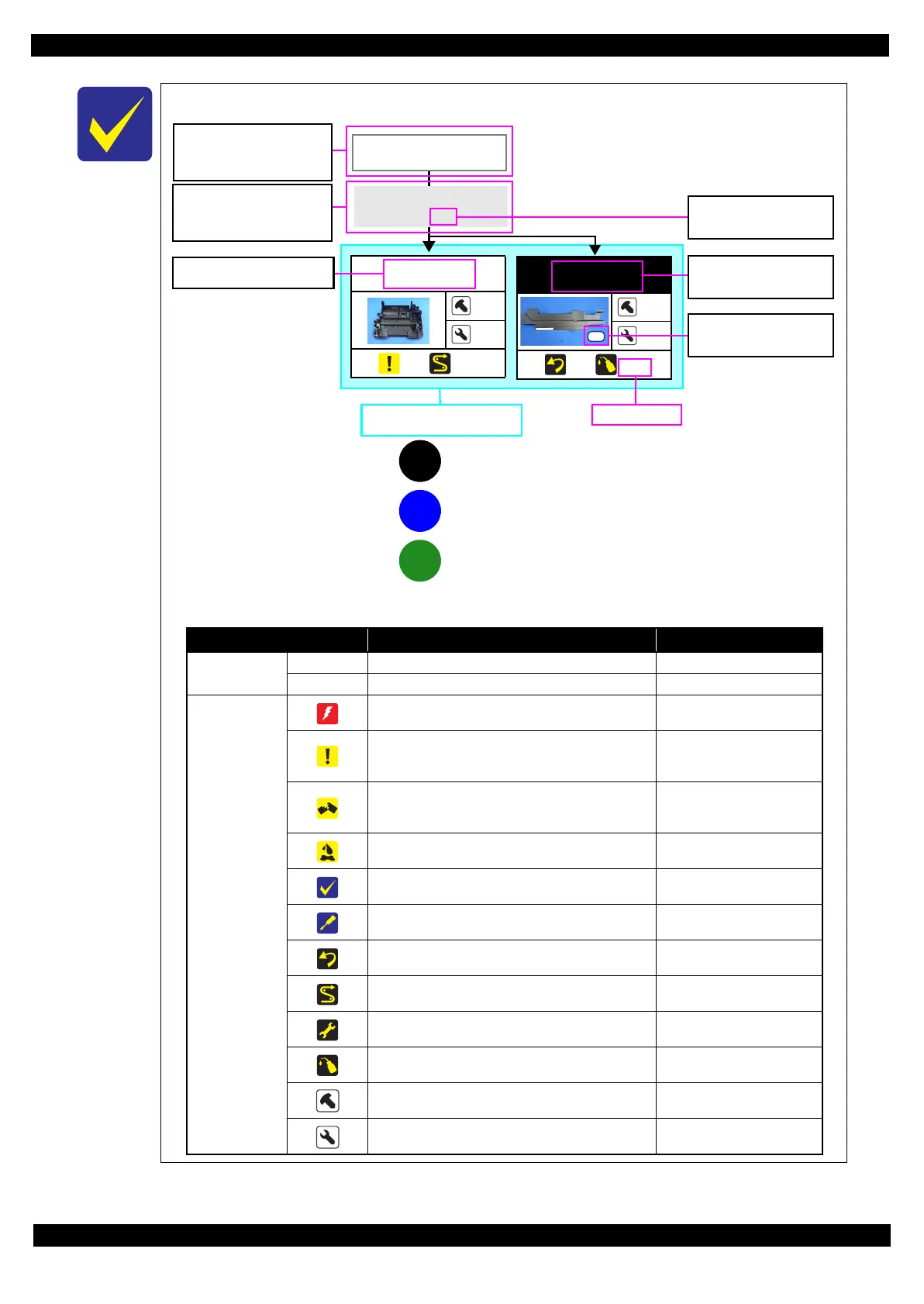
The example below shows how to see the charts on the following pages.
Housing Rear
1
4
(p22) (p43)
S4
Frame Base Assy
---
---
(p21) (p27)
Paper Guide
Upper Assy (p29)
CR Timing Belt
FFC/ Cable *1
Shows necessary
procedures before
removing the following
parts.*
Black letters indicate a part/
unit not supplied as an ASP.
Item Description Reference
Parts/unit name
White-letter
Part/unit supplied as an ASP ---
Black-letter
Part/unit not supplied as an ASP ---
Icon
Indicates a practice or condition that could result in
injury or loss of life if not strictly observed.
Indicates the reference page
in blue-letter
Indicates a practice or condition that could result in
damage to, or destruction of equipment if not strictly
observed.
Indicates the reference page
in blue-letter
Indicates the parts that are inevitably broken in the
disassembling procedure, and should be replaced with
a new one for reassembly.
Indicates the reference page
in blue-letter
Indicates the parts that may cause the ink spill when
they are removed.
2.1.5Checks and Precautions
before Disassembling (p26)
Indicates necessary check items in the disassembling/
assembling procedure.
Indicates the reference page
in blue-letter
Indicates supplementary explanation for disassembly
is given.
Indicates the reference page
in blue-letter
Indicates particular tasks to keep quality of the units
are required.
Indicates the reference page
in blue-letter
Indicates particular routing of cables is required.
Indicates the reference page
in blue-letter
Indicates particular adjustment(s) is/are required.
Chapter 3 " Adjustment
(p59)"
Indicates lubrication is required.
Chapter 4 " Maintenance
(p73)"
Indicates the number of screws securing the parts/
units.
---
Indicates the points secured with other than a screw
such as a hook, rib, dowel or the like.
---
White letters indicate a
part/unit supplied as an
ASP.
Shows the screw types and
the specified torque on the
“Screw type/torque list”.
Reference page
Shows removal/installation
as a unit/assy. is available.
The name enclosed in gray
indicate a part/unit that
must be removed on the
way to the target parts.
Note "*": The box with only part names means the removal of the parts. If the name of
FFC or a cable is shown, disconnect the FFC or cable from the connector.
Shows the procedure
number on the “FFC/
cable list”.
1
i
A
: Indicates the connection to the disassembly flowchart for the Unit/Assy
: Indicates the connection between the disassembly flowchart
: Indicates the connection to the Common Printer Mechanism
 Loading...