M200 / M205 / M100 / M105 Series Revision A
Disassembly/Reassembly Detailed Disassembly/Reassembly Procedure for each Part/Unit 48
Confidential
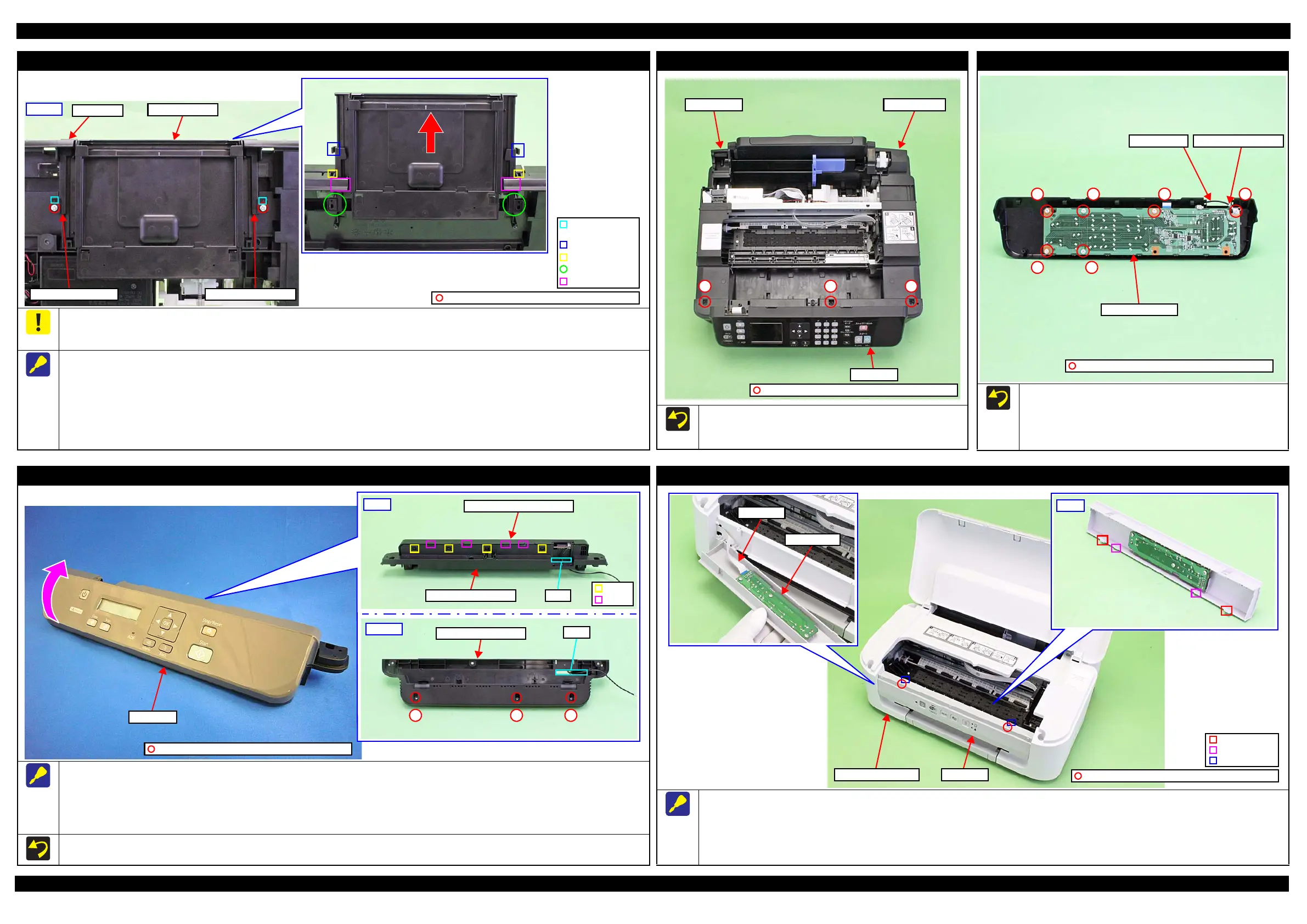
Tray Front Rail Left/Tray Front Rail Right, Tray Front Assy (M100/M105 Series)
Make sure to remove the Tray Front Assy and Tray Front Rail Left/Tray Front Rail Right after releasing the ribs on the Tray Front Rail Left/Tray
Front Rail Right from the grooves on the Frame Base. If the Tray Front Assy or Tray Front Rail Left/Right are forcibly removed if the ribs are
engaged in the grooves, the ribs may be damaged.
When removing the Tray Front Rail Left/Tray Front Rail Right and Tray Front Assy, follow the procedure below.
1. Remove the screws (x1 each) of the Tray Front Rail Left/Tray Front Rail Right.
2. Release the positioning holes (x1 each) of the Tray Front Rail Left/Tray Front Rail Right from the dowel (x2) of the Frame Base.
3. Pull the Tray Front Assy and Tray Front Rail Left/Tray Front Rail Right together, and release the ribs (x1 each) of the Tray Front Rail Left/Tray
Front Rail Right from the grooves of the Frame Base.
4. While releasing section A on the Tray Front Rail Left/Tray Front Rail Right from section B on the Frame Base, remove the Tray Front Assy and
Tray Front Rail Left/Tray Front Rail Right together.
C.B.P-TITE SCREW 3x10 F/ZN-3C (6 ± 1 kgf·cm)
Tray Front Rail Left Tray Front Rail Right
Tray Front Assy
Frame Base
Dowel and
positioning hole
Groove
Rib
Section A
Section B
Bottom
Panel Unit (M200/M205 Series)
Tighten the screws (x3) securing the Panel Unit after installing
the Housing Left/Housing Right.
Tighten the screws in the order indicated in the figure above.
Panel Unit
Housing RightHousing Left
12 3
C.B.P-TITE SCREW 3x10 F/ZB-3C (6 ± 1 kgf·cm)
Panel Board Assy (M200/M205 Series)
Tighten the screws in the order indicated in the figure above.
Tighten the grounding wire together on the position indicated
in the figure above.
Tighten the grounding wire with screws on the direction
indicated in the figure above.
Panel Board Assy
1
Grounding wire
2
3
4
5
6
C.B.P-TITE SCREW 3x10 F/ZN-3C (6 ± 1 kgf·cm)
Grounding wire terminal
Panel Housing Upper Assy (M200/M205 Series)
When removing the Panel Housing Upper Assy, follow the procedure below.
1. Remove the screw (x3) of the Panel Unit.
2. Rotate and lift the front side of the Panel Housing Upper Assy and remove the hook (x4) and rib (x5) from the Panel Housing Upper Assy.
3. Pull out the grounding wire of the Panel Housing Upper Assy from the hole of the Panel Housing Lower Assy and remove the Panel Housing
Upper Assy from the Panel Housing Lower Assy.
Tighten the screws in the order indicated in the figure above.
Rear
Hook
Rib
Panel Housing Upper Assy
Panel Housing Lower Hole
Panel Unit
Bottom
Panel Housing Lower
Hole
123
C.B.P-TITE SCREW 3x10 F/ZB-3C (6 ± 1 kgf·cm)
Panel Unit (M100/M105 Series)
When removing the Panel Unit, follow the procedure below.
1. Remove the screw (x2) securing the Panel Unit.
2. Remove the hole (x2) from the dowel(x2) of the Housing Upper Assy.
3. Remove the hook (x2) and rib(x2) on the back of the Panel Board from the Housing Upper Assy.
4. Remove the Panel FFC from the connector (CN1) of the Panel Board and remove the Panel Unit.
Back
Panel Board
Panel FFC
Panel UnitHousing Upper Assy
Hook
Rib
Dowel and hole
C.B.P-TITE SCREW 3x10 F/ZN-3C (6 ± 1 kgf·cm)
 Loading...