M200 / M205 / M100 / M105 Series Revision A
Disassembly/Reassembly Detailed Disassembly/Reassembly Procedure for each Part/Unit 51
Confidential
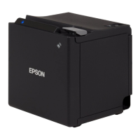
Wireless LAN Module (M205/M105 Series)
Attach two pieces of acetate tape on the Wireless LAN Module
cable to cover the cable to protect it as shown above.
Wireless LAN Module
Wireless LAN Module Cable
Wireless LAN Module Cable
Cover with acetate tape (x2).
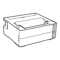
PF Grounding Spring
When installing the PF Grounding Spring, follow the procedure below.
1. From the left side of the printer, insert the spring leg A of the
PF Grounding Spring into the hole of the Frame Base.
2. Insert the spring leg B of the PF Grounding Spring into the
groove of the Frame Base.
3. Attach the spring leg B of the PF Grounding Spring to the
cutout of the Main Frame to install the PF Grounding Spring.
Insert spring leg
A into groove.
PF Grounding
Spring
Main Frame
Left
Cutout
Spring leg B
Spring leg A
Spring leg B
PF Grounding
Spring
Frame Base
Assy
Hole
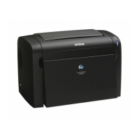
PF Scale Sheet
Attach the PF Scale Sheet to the Main Frame according to the
standard indicated in the figure above.
Main FramePF Scale Sheet
Double-sided tape
Align the corner of Main Frame.
Align the edge of Frame Base. Insert the outside the
rib of Frame Base.
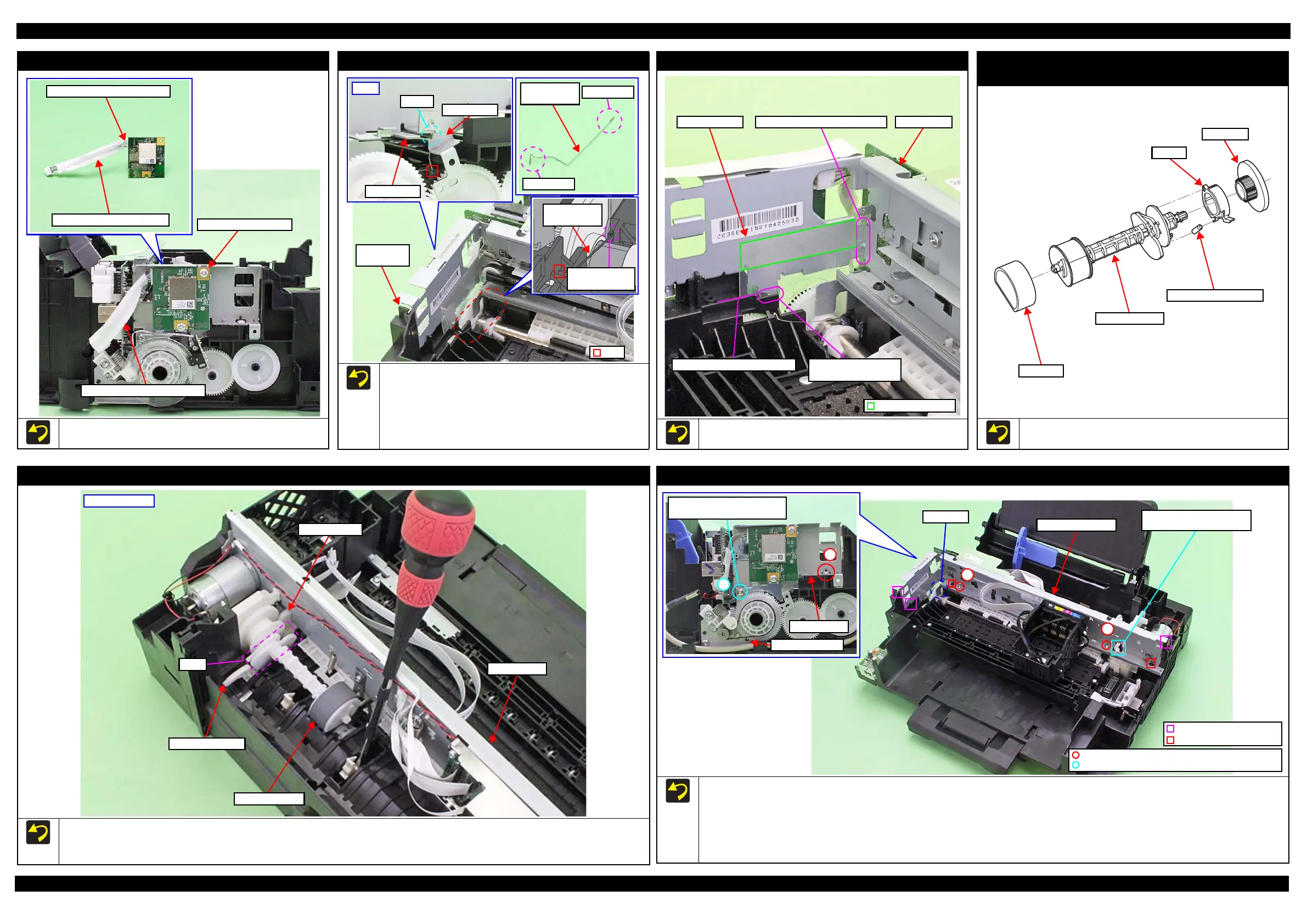
Spur gear / Extension Spring 0.137 /
Clutch / LD Roller shaft
Install Spur gear/Extension Spring 0.137/Clutch/LD Roller shaft as
shown in the figure above.
Extension Spring 0.137
Clutch
Spur gear
LD Roller Shaft
LD Roller
LD Roller Assy
Install the LD Roller Assy with the following condition in order to avoid the Change Lever and Paper Back Lever.
Using a screw driver or the like, hold the Paper Back Lever to the rear as shown above not to let it touch the LD Roller Assy.
Push the Change Lever to the front to keep it in the hole of the Main Frame.
LD Roller Assy
Paper Back Lever
Change Lever
Cam
Main Frame
Rear of printer
Main Frame Assy
Before installing the Main Frame Assy, shift the Change Lever back to the rear.
When installing the Main Frame Assy, make sure of the following.
• The Change Lever must not interfere with the Main Frame.
• The above shown ribs and grooves, positioning holes and dowels are correctly aligned.
• The section A of the Main Frame Assy is not deformed.
Tighten the screws in the order indicated in the figure above.
3
4
PF Motor Frame
Main Frame
Align the screw holes of Main
Frame and PF Motor Frame.
1
2
Section A
Main Frame Assy
Change Lever must not
interfere with Main Frame.
C.B.P-TITE SCREW 3x10 F/ZN-3C (6 ± 1 kgf·cm)
C.B.S-TITE SCREW 3x6 F/ZN-3C (6 ± 1 kgf·cm)
Rib and groove
Positioning hole and dowel
 Loading...