22
Eubank EAA/EGA Wall Mount AC Installation & Operation Manual
03/2021 Rev.5
Item Description
1 Outdoor Motor Control Signal Output
2 Indoor Motor Control Signal Output
3
P 1/2- Pressure for Circuit 1 and Circuit 2 (Respectively)
FS1 – Freeze Stat for Circuit 1
FS2 – Indoor Temperature Input
4
Modbus Communication
3 Wire [A, B, COM] and Parallel RJ-11 Port
5
6
Fan Cycle Control Input (only Applicable for EC Outdoor Motors)
Hum – Humidity Control Input (Connect to R Node)
Y 1/2 - Cooling Request for Stage 1 and Stage 2 Cooling Operation
7 Modbus Network Address. Set All 4 to OFF for Local Control
8 Potentiometers for Indoor and Outdoor Speed
9 Energize or De-Energize Test Mode
10 Set Speed of Indoor Motor for Y1 and Y2 Operation
11 Set Baud Rate. 19.2k Between Top and Mid. 9.6k Between Mid and Bottom
12 Set Indoor Motor Control Signal Type
13 Set Outdoor Motor Control Signal Type
14
Thermostat Inputs:
W2 – Heat Request
G – Indoor Fan Request
ON – Connect Respective Terminal to R Node.
Off – Open Circuit
15
Pressure Switch Inputs for Respective Circuit
HP – High Pressure Switch
LP – Low Pressure Switch
Switch to Be Closed for Cooling Operation. Switch to Be Connected to “R” Node
16 24 VAC Power Input to PCB.
17
Digital Outputs (24 VAC): The PCB Makes and Breaks R.
RH – Reheat
EH – Electric Heat
CC 1/2– Compressor (Respectively)
18 Alarm Contacts
2.2 Installation and Replacement
The PCB is factory installed. To install a replacement PCB, use the six mounting holes along with the
appropriate screw size to rmly secure the board to the control box. After this is achieved, follow the
wiring diagram and pin conguration for the respective system for appropriate operation. Ensure that
the terminals used do not make any unwanted electrical connection (via strands etc.) with any other
terminals. Please allow a 1” creepage distance between the board and all other adjacent electrical
components.
2.3 Operation
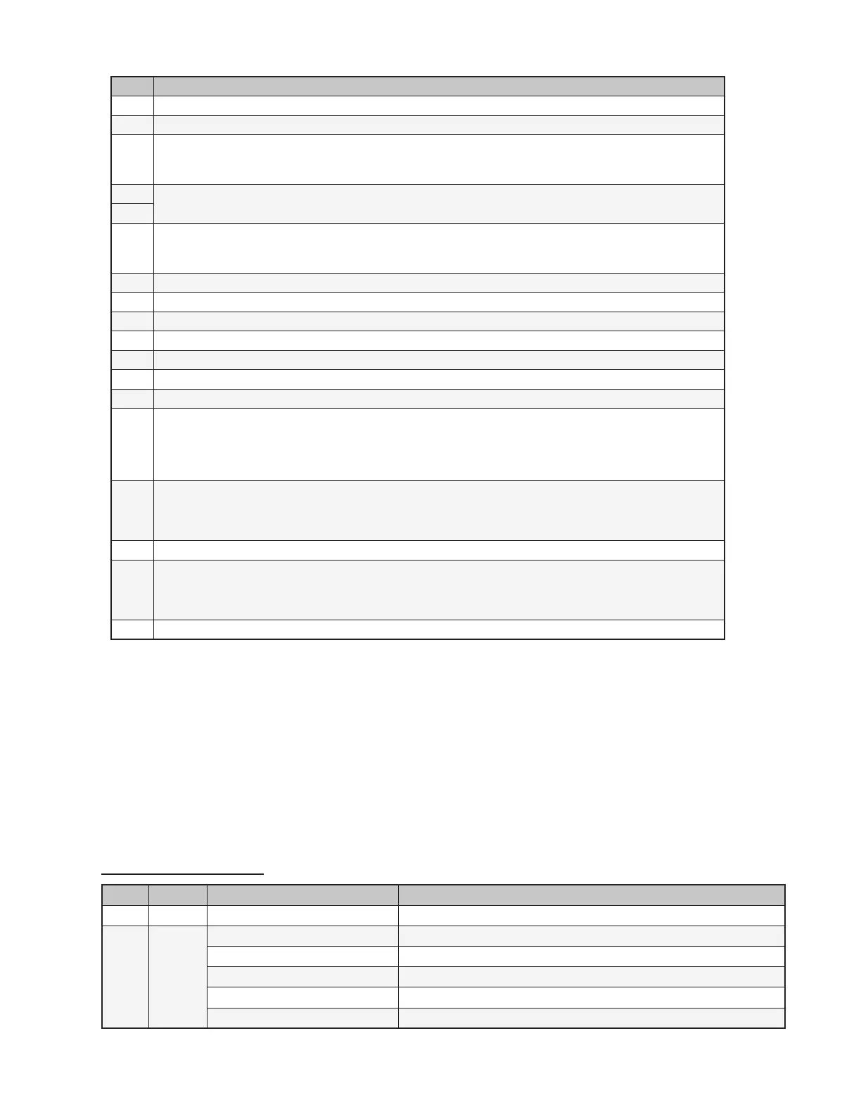
LED Status Indicators
Color Type Status Description
Green Power Constant On 24 VAC power has been applied
Red
Status 1
and
Status 2
Constant On Normal Operation
1 Blink High pressure switch has opened twice
2 Blinks Low pressure switch has opened twice
3 Blinks Freeze stat (optional) - Indoor coil temperature is below 35°F (1°C)
Continuous Flash of Both LEDs Insufcient voltage to the board. Less than 20 Volts
 Loading...