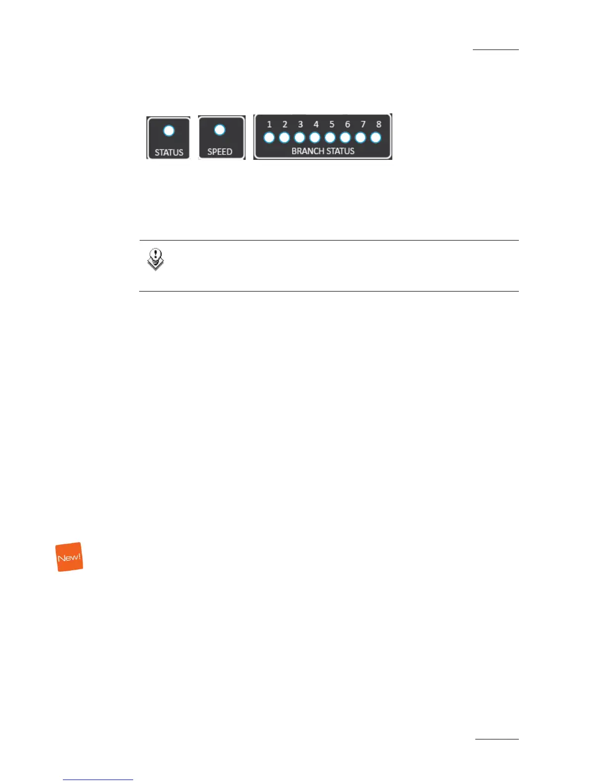
2.3.4 STATUS, SPEED AND BRANCH STATUS LEDS
Those LEDs match the corresponding front LEDs.
2.3.5 INPUT AND OUTPUT BNC CONNECTORS
8 input BNC connectors and 8 output BNC connectors are used to connect devices
in the SDTI network.
Note
The IN and OUT connectors are opposite of the XHub[2] series. On a
XHub3, the Input connectors are located on the top row.
2.4 INTERCONNECTING XHUBS
2.4.1 PURPOSE
When more than 8 XNet branches are required, it is possible to connect several
XHubs to a master XHub to obtain the required number of branches. In this case
please make sure that the rules specified below are followed.
2.4.2 RULES
• One and only one XHub must be configured as MASTER XHub. All other hubs
must be configured as SLAVE XHubs.
• The 1
st
branch of a SLAVE XHub must be used as the uplink branch to the
MASTER XHub.
• All SLAVE XHubs must connect directly back to the MASTER XHub; a SLAVE
XHub cannot be connected to another SLAVE XHub. Maximum configuration is
therefore 1 MASTER XHub connected to up to 8 SLAVE XHubs.
• A MASTER XHub does not need to have any servers connected to it, and can
consist completely of 8 Slave Hubs.
 Loading...