8
F7
TF1
DS1
SW1
F5
J1
J3
LK1
F6
LED
J5
RL6
RL7
F2
J4
J2
RL8
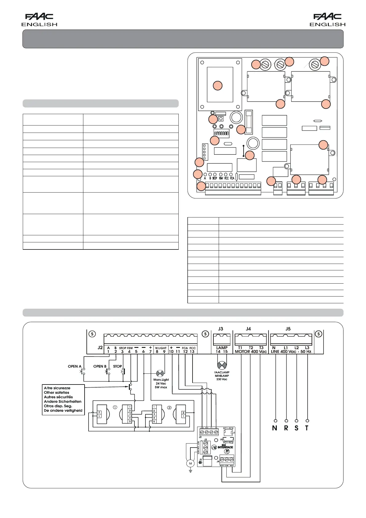
CONTROL BOARD 844 T
These instructions apply to the following model:
844T Electronic control unit
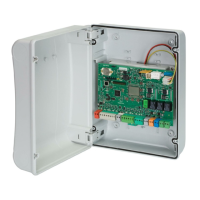
This appliance can be installed in containers mod. E, L and
LM. Before securing the card in the container, fit the supplied
support feet (long for mod. E, short for models L and LM) in the
3 S-holes (Fig.1).
2. ELECTRICAL CONNECTIONS WITH 400V 3ph (N.B.: for connection to 230 V 3ph, see Chapter 8)
Fig. 1
1. TECHNICAL SPECIFICATIONS
ylppusrewoP
).zH05%01-%6+(hp3.caV032
).zH05%01-%6+(N+hp3.caV004
daolxamrotoM
.wK3,1
ylppusrewopseirosseccA
.cdV42
daolxamseirosseccA
.Am005
ylppusrewopthgilgininraW
).ttaW5xam(.caV42
egnarerutarepmeT
C°55+C°02-
sesuF
)1.baT(7F,6F,5F,2F
sgulptif-kciuQ
sreviecerPRrosdracgnidoced
stupnI
/NEPOLAITRAP/NEPO
/ECIVEDYTEFASERUSOLC/POTS
SROSNES-TIMIL
stuptuO
thgilginraw
thgilhsalf
rotom
seirossecca.cdV42otylppusrewop
gnimmargorP
06-03-51-01-5(emitesuap
).ces081-021
C/B/2E/1E/2S/1S/2A/1Ascigol
gnihsalf-erp
gnikarbrotoM
dexif
gnimitytefaS
.ces552
7F-6F-5F
)sesufylppusrewop(diparV052/A523x3,61FesuF
2F
)seirossecca(diparV052/A6,102x52FesuF
1WS
nottub-hsupTESER
1SD
sehctiwsorcimgnimmargorP
DEL
ACF,CCF,WSF,POTS,B,AsDELgnillangissutatstupnI
1J
sreviecerPR/sdracgnidocedrofgulptif-kciuQ
2J
seirossecca/stupnirofdraoblanimretegatlovwoL
3J
)W06xam~V032(draoblanimrettuptuothgilhsalF
4J
draoblanimrettuptuorotoM
5J
draoblanimrettupniylppusrewopeniL
1KL
tcatnoceerfthgilgninrawrofegdirB
7LR-6LR
yalerrotoM
8LR
yalergnikarB
Tab. 1 - 844 T CONTROL UNIT COMPONENTS
 Loading...