1
0
70
32,5
90
105
98
DL1
SW1
SW2
DL2
CH1 CH2
5
DL3
6
7
8
10
11
12
+
9
1 2
N.O.
N.O.
DS1
1
4
2
3
ENGLISH
2 TECHNICAL SPECIFICATIONS
XR2 433 C - XR2 868 C
XR2 433 C XR2 868 C
POWER SUPPLY (V) 12/24 ac-dc 12/24 ac-dc
RECEPTION FREQUENCY (MHz) 433.92 ±0.1 868.35±0.2
ABSORBED CURRENT (A) 100 mA 100 mA
DECODING (OMNIDEC SYSTEM) DS-LC-SLH DS-SLH
SAVEABLE CODES 250 250
NUMBER OF CHANNELS 22
NUMBER OF RELAY OUTPUTS (N.O.) N 1 pulsed (CH1)
N 1 pulsed/fixed (selectable) (CH2)
N 1 pulsed (CH1)
N 1 pulsed/fixed (selectable) (CH2)
RELAY CONTACTS CAPACITY 0.5 A / 120 VA 0.5 A / 120 VA
PROTECTION CLASS IP 44 IP 44
OPERATING AMBIENT TEMPERATURE (°C)
-20 / +55 -20 / +55
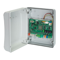
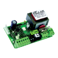
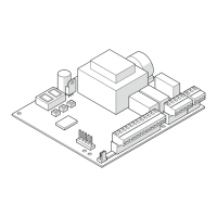
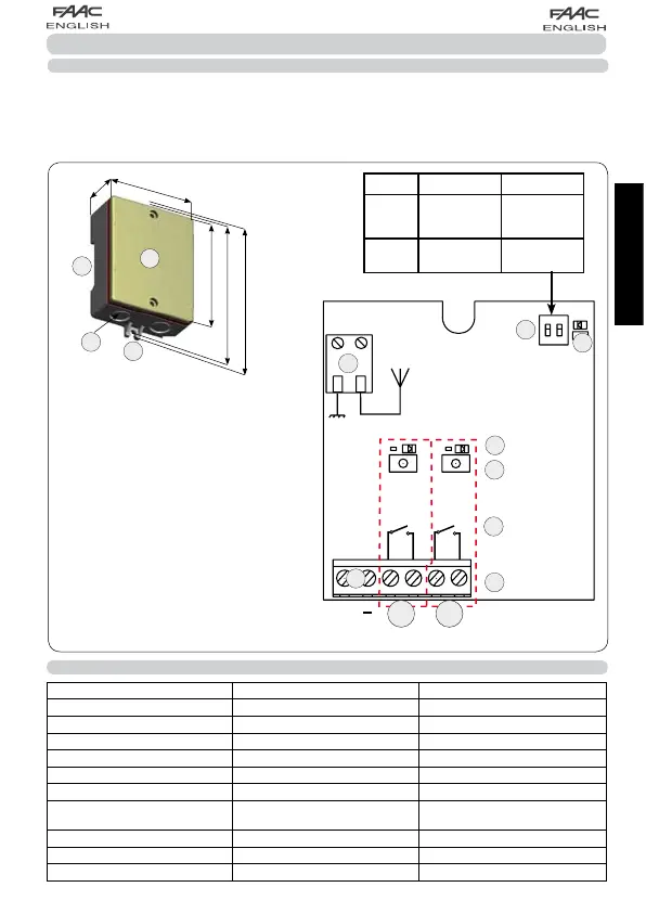
/Preperforated facility for cable grippers
0Cover
1Facility for securing on DIN guide
2Fittings for screw securing
3 Terminals for command output (N.O.)
4 Normally open (N.O.) relay contact
5 Signalling LEDs (ON= OUTPUT ACTIVE)
DL1=LED CH 1 DL2=LED CH2
6 Radio programming push-buttons
SW1=PUSH-BUTTON CH1
SW2=PUSH-BUTTON CH2
7DS1:Selection dip-switch
8 Power supply terminal
9 Terminal for antenna
: DL3: Mains ON LED ( ON = MAINS PRESENT )
1 DESCRIPTION
The XR2 C control board is a two-channel external receiver, which has an integrated decoding system (DS, SLH, LC),
named OMNIDEC. When a channel is activated by radio control (DS, SLH, LC), the relevant N.O. relay contact closes
by the methods described in chapter 5.
The selectable configurations are:
CH1 = pulsed N.O. relay output
CH2 = pulsed/fixed N.O relay output (selectable by DS1)
Fig.1
DS1 ON OFF
DIP
SWITCH 1
OUTPUT
CHANNEL 2
FIXED
OUTPUT
CHANNEL 2
PULSED
DIP
SWITCH 2 NOT USED NOT USED
 Loading...