CHAPTER
3
Manual No. 016-5030-043 Rev. A 9
C hapter 3
Mechanical Drive
Installation
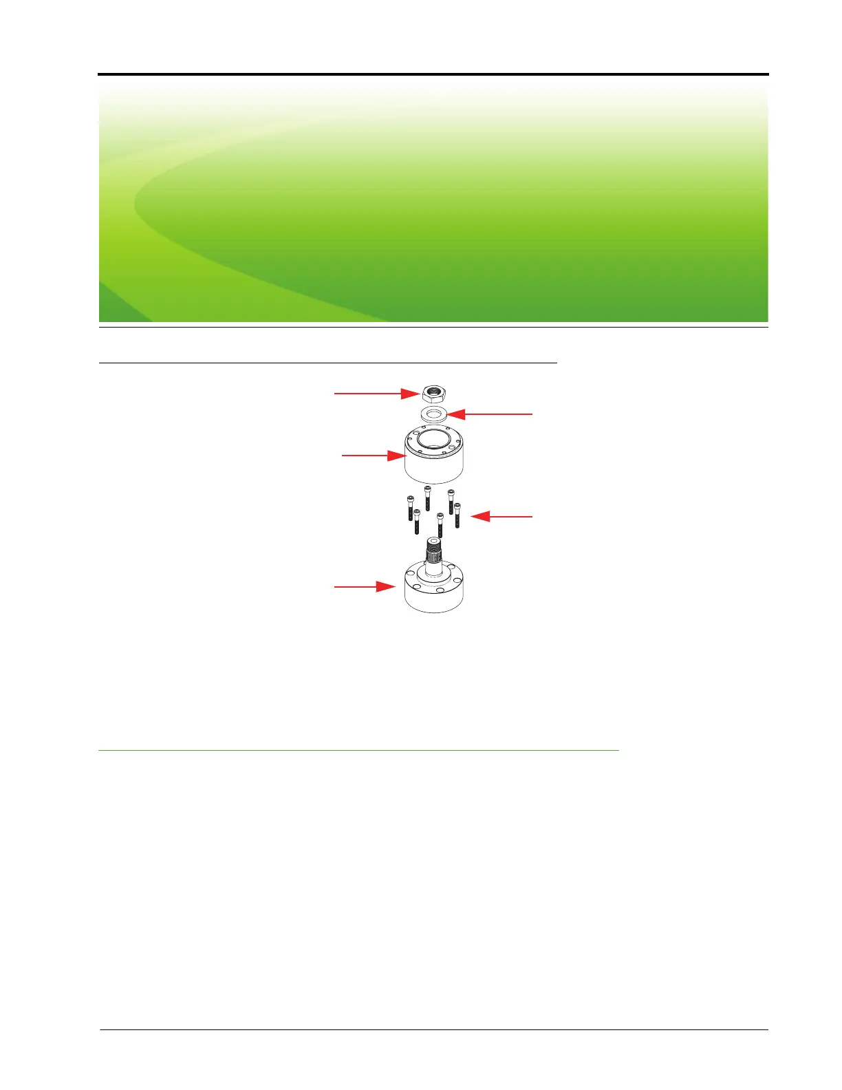
FIGURE 1. Spline Assembly Disassembled
1. Locate the 20 mm x 36 tooth spline adapter assembly (P/N 063-4001-022).
2. Disassemble the spine adapter assembly as shown in Figure 1 above.
Remove the Steering Wheel
Note: The steps in this section require use of a steering wheel puller (not supplied). For questions on the
proper procedure for removing the steering wheel, contact your local equipment dealer.
Nut
Washer
Female Spline
Adapter
Bolts
Male Spline
Adapter
 Loading...