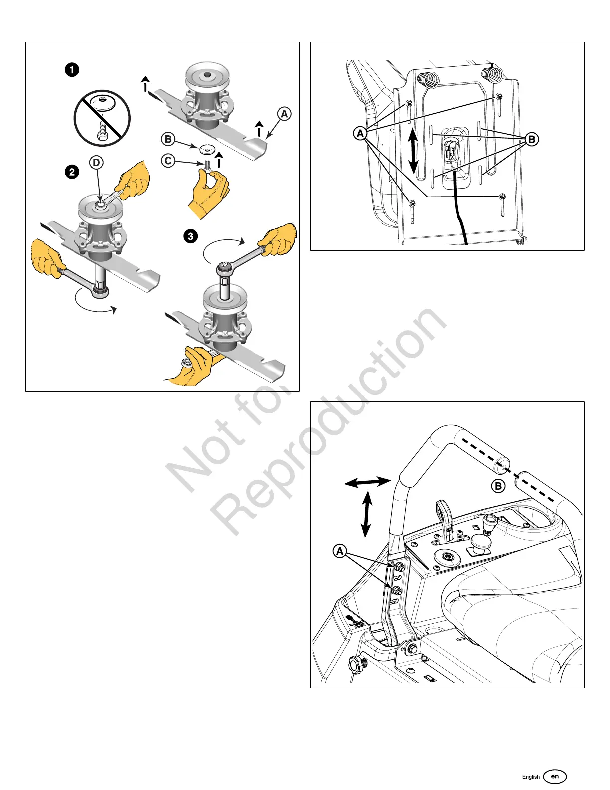
29
31
2. Tighten the blade mounting bolt to 50 - 60 ft. lbs. (68 - 81
Nm) of torque while holding onto the pulley bolt (D) with a
wrench.
3. Tighten the pulley bolt to 50 - 60 ft. lbs. (68 - 81 Nm) of
torque while holding onto the blade mounting bolt with a
wrench.
Seat And Ground Speed Control Lever
Adjustments
The seat and ground speed control levers should be adjusted
so that the ground speed control levers can be moved
through their full range of motion without contacting the
operator’s legs.
Seat Adjustment
1. Raise the seat.
2. Loosen the adjustment hardware (A or B, Figure32,
depending on seat type) under the seat base.
3. Slide the seat forward or backward to the desired
position.
4. Tighten the hardware to 80 lb-in (9 Nm).
32
Ground Speed Control Lever Adjustment
1. Loosen the ground speed control lever mounting
hardware (A, Figure33)to adjust the levers forward and
backward.
2. Remove the hardware to raise or lower the levers.
3. Always be sure to adjust both levers so that they are
aligned (B, Figure33).
4. After adjustment is complete, tighten the hardware to 13
lb-ft (18 Nm).
33
Speed Balancing (Tracking) Adjustment
If the unit drifts to the right or left when the ground speed
control levers are in the maximum forward position, the top
speed of each of these control levers can be balanced. Only
adjust the speed of the wheel that is traveling faster.
 Loading...