page 10 of 12
MULTIPLE VENTING SYSTEMS
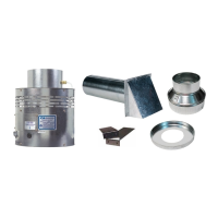
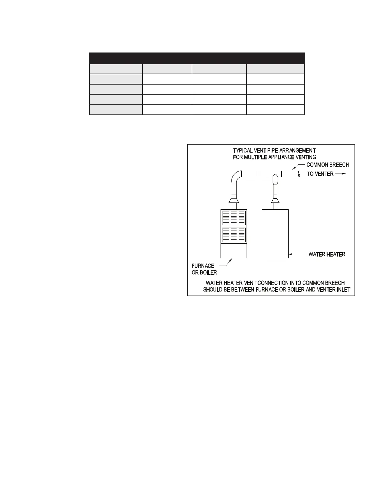
1. To vent a 24 VAC controlled boiler or furnace and a
30 millivolt residential water heater using one PVG
power venter refer to the following.
a. Follow the instructions for safe and proper
venting previously speci ed in this manual.
Make sure that the combined gross BTU/HR
input and equivalent vent pipe length does not
exceed the maximum venting capacity of the
venter selected.
b. A CK-20FV or CK-20FG control kit MUST be
added to the system to properly control the
venter during operation of the water heater.
Refer to Figure 10 and Diagrams C and D for
vent pipe arrangement and wiring information.
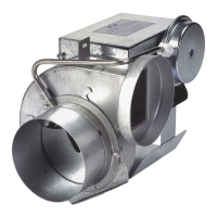
2. To vent two 24 VAC appliances using one PVG
power venter refer to the following.
a. Follow the instructions for safe and
proper venting previously speci ed in
this manual. Make sure that the combined
gross BTU/HR input and equivalent vent pipe length does not exceed the maximum venting capacity of
the venter selected.
b. A CK-41 Control Kit must be added to the system to properly control the venter when common venting an
additional 24 VAC furnace or boiler. Tee the draft tube on the PVG unit to connect to the air pressure switch
on the Control Kit. Refer to Diagram D for wiring instructions.
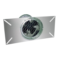
PV SERIES POWER VENTER: VERTICAL VENTING OPTION
Diagram C illustrates correct and incorrect installation of PV series venter in vertical vent con guration (except
PVE-1200). The correct installation maintains the required vertical position of the pressure switch; the incorrect
installation does not. The following conditions must also be observed:
• Natural gas, LP gas or #2 fuel oil appliance rated at 75% or greater non-condensing type of appliance
• Maximum input temperature at power venter: 575°F
Figure 10
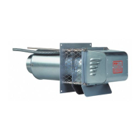
REPLACEMENT PARTS LIST
The following items are available for replacement, if necessary.
REPLACEMENT PARTS LIST
DESCRIPTION PVG-100 PVG-300 PVG-600
Motor 46032000 46032000 46083300
Blower Wheel 46080100 46033400 46089400
24 VAC Relay 46282800 46282800 46282800
Pressure Switch 602602001 602602002 602602003
P/N 46246300 Rev M 04/20
 Loading...