page 11 of 12
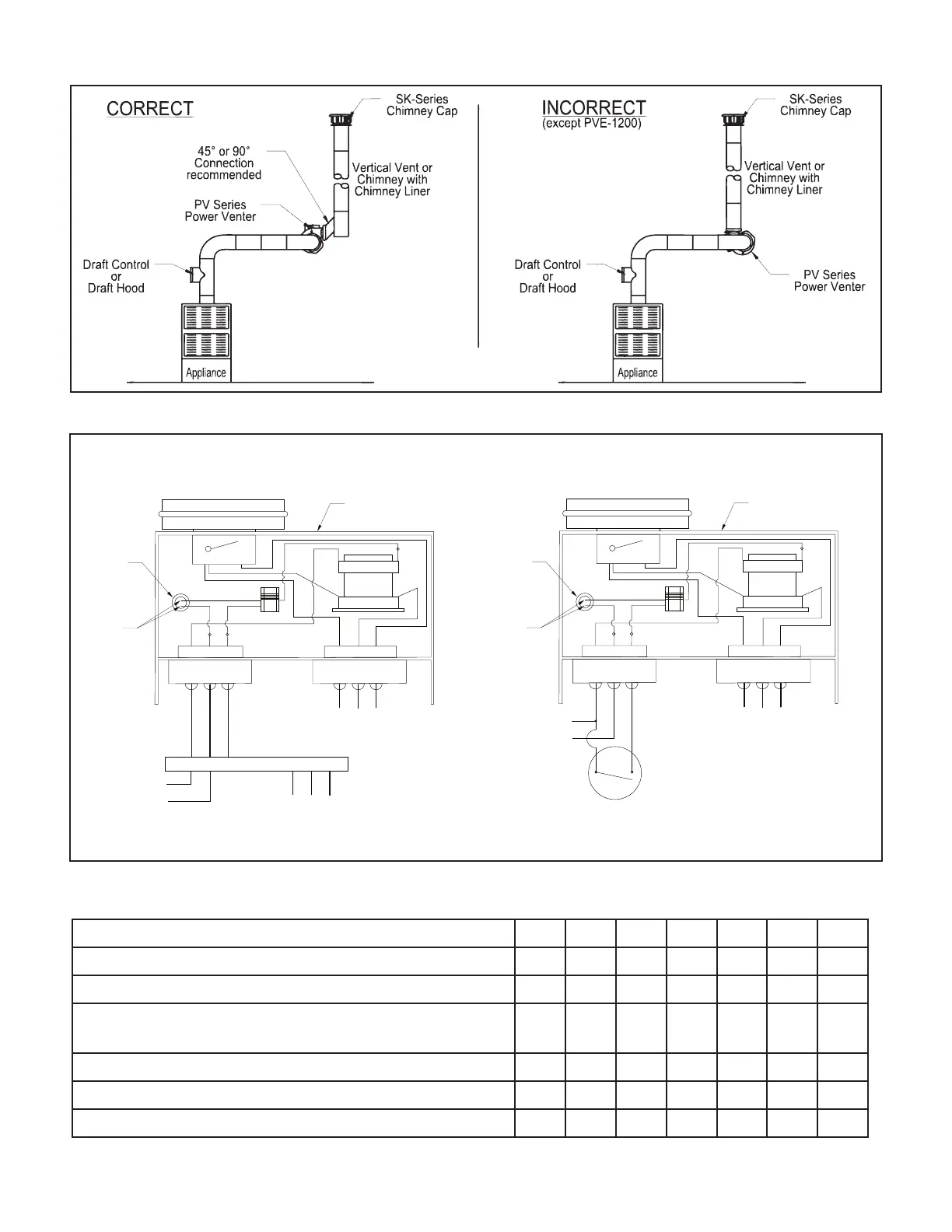
Diagram D
LNM
T
1
T
RELAY/TIMER
N/OCOM
PLASTIC
BUSHING
AIR PRESSURE SWITCH
PVG JUNCTION BOX
MOTOR
LEADS
13
2
T
3
LNM
T
1
T
RELAY/TIMER
N/OCOM
PLASTIC
BUSHING
AIR PRESSURE SWITCH
PVG JUNCTION BOX
MOTOR
LEADS
13
2
T
3
APPLIANCE
CONNECTIONS
L1 N M
T1 T2 T3
APPLIANCE
CONNECTIONS
L1
L2
TERMINAL STRIP IN 24VAC
CONTROL KIT ON SECOND APPLIANCE
APPLIANCE
CONNECTIONS
L1
L2
GAS PRESSURE SWITCH
ON MILLIVOLT APPLIANCE
PVG WIRING FOR MULTIPLE 24VAC APPLIANCES
PVG WIRING FOR MULTIPLE 24VAC APPLIANCES
VENTING SYSTEM OPERATIONAL INFORMATION
Date:
Heating appliance BTU/HR input
Gas valve operation pressure
Vent system draft above draft hood or below
barometric draft control
CO
2
measurement
CO measurement
Appliance outlet ue gas temperature
P/N 46246300 Rev M 04/20
Diagram C
 Loading...