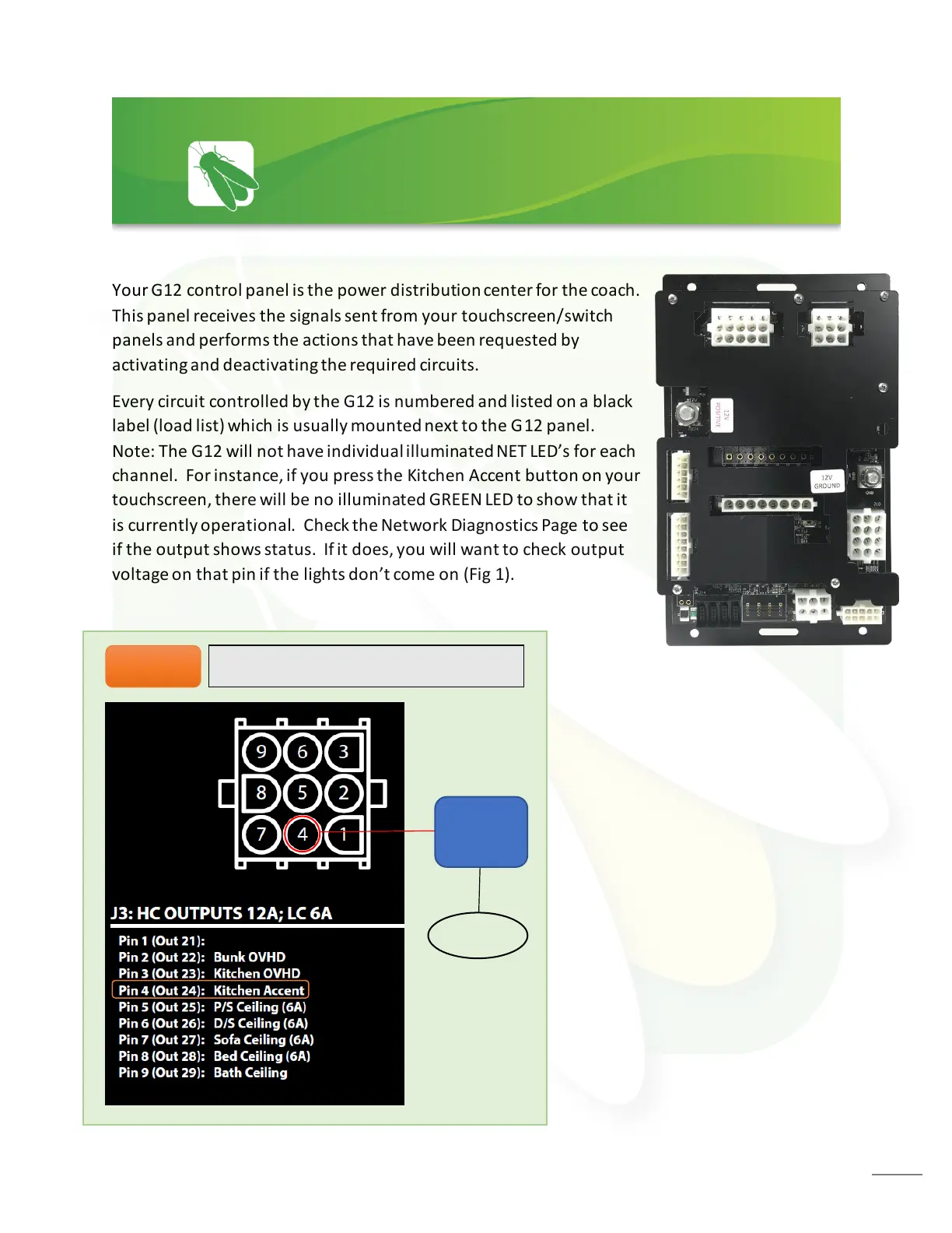
Your G12 control panel is the power distribution center for the coach.
This panel receives the signals sent from your touchscreen/switch
panels and performs the actions that have been requested by
activating and deactivating the required circuits.
Every circuit controlled by the G12 is numbered and listed on a black
label (load list) which is usually mounted next to the G12 panel.
Note: The G12 will not have individual illuminated NET LED’s for each
channel. For instance, if you press the Kitchen Accent button on your
touchscreen, there will be no illuminated GREEN LED to show that it
is currently operational. Check the Network Diagnostics Page to see
if the output shows status. If it does, you will want to check output
voltage on that pin if the lights don’t come on (Fig 1).
 Loading...