ADS Blade Cartridge Slot and Connector
This is the main feature of the CM5000 and CM5200. The slot gives you the ability to use the Blade-AL
and Blade-TB modules from Firstech and ADS. With these modules you can virtually eliminate all wire
connections between your control module and bypass module. You only need to connect the main
ignition harness and your needed wires on the 20 pin Blade connector. For more information on how to
program and wire the Blade please visit
www.idatalink.com/compustar for the specific wiring diagram for
that vehicle.
Blade system includes:
1. Blade-AL or Blade-TB (NOTE: These modules are blank and must be flashed on your computer.)
2. 20 Pin wiring harness
3. 3 Pin harness used in some installs
IMPORTANT: Install diagrams are not included and must be downloaded from
www.idatalink.com/compustar. When flashing the Blade you can use the Y-Cable OP500 end and not
CM4 Series end. ADS and Firstech recommends using the 4 pin RS232 cable to avoid confusion.
Cartridge must be removed to flash the control module firmware.
NOTE: The ADS-RNG C1, ADS-RNG C2, and ADS-RNG GM3 are not included and must be purchased
separately. The 20 pin Blade connector comes only with the Blade cartridge and not the CM5 control
modules.
WARNING: Manufacturer or seller will have no responsibility for any injuries and/or damages caused by
improper care of the product such as decomposition, conversion, and transform done by a user
voluntarily. WARNING: There should be no wiring routed around any pedals which
can cause a driving hazard.
10
19
Option Programming Tables
OPTION GROUP 1
Feature Default Setting - I Optional Setting - II Optional Setting - III Optional Setting - IV
1-01 Unlock before, Lock after, starting Off On
Lock After Remote Start
Only
Lock After Shutdown
Only
1-02 Lock / Unlock pulse duration 0.8 sec 2.5 sec 0.125 sec 3.5 sec
1-03 Driver's priority unlock Off On
1-04 Double pulse unlock Off On
1-05 Rearm Output
After Start Shutdown
and First Lock
After Shutdown Only
1-08 Locking while in Passive Arming
Passive locking with
Passive Arming
No Passive Locking with
Passive Arming
1-09 Ignition controlled door locks Off On
1-11 Ignition / Accessory Out Upon Unlock Off
Ignition and Acc Pulse -
same timing as disarm
pulse
1-13 Double Pulse Disarm Input Single Pulse Double Pulse
1-14
Auto Lock Mode (2 Way International
Remotes)
Off On
OPTION GROUP 2
Feature Default Setting - I Optional Setting - II Optional Setting - III Optional Setting - IV
2-01 Tach Sensing Method Optimal Tach Method Previous Tach Method
Low Threshold Tach
Method
2-02 Turbo Timer Off 2 Min
2-03 Diesel Timer Wire 3~99sec (10sec Default) 5 Sec. Delay 15 Sec. Delay
2-04 Trigger Start Off Single Pulse Double Pulse Triple Pulse
2-06
Timer Start, or, Minimum Interval
Between Cold Starts
3 Hour (4 minute
runtime, double for
Diesel)
1.5 Hour(4 minute
runtime, double for
Diesel)
2-07 Remote Start Runtime 15 Min 25 Min 45 Min 3 Min
2-10 Engine Sensing Tach Alternator
No Connection –
Voltage Sensing
Not for Manual
Transmissions
No Connection – 1.5
Second Crank Not for
Manual Transmissions
V.1 or greater
2-12 Crank Time Standard
+0.2 Seconds to Crank
Time
+0.6 Seconds to Crank
Time
(Voltage Sensing Only)
(-)0.2 Second Crank
Time
OPTION GROUP 3
Feature Default Setting - I Optional Setting - II Optional Setting - III Optional Setting - IV
3-03 Dome Light Delay Off Auto
3-04 Starter-Kill Relay Anti-Grind + Starter Kill Anti-Grind
Anti-Grind +
Passive Starter Kill
3-06 Factory Alarm Option (CM5200 Only) Off On
3-07 Siren Duration (Upon Alarm Trigger) 30 Sec. 60 Sec.
3-08 Horn Output (CM5200 Only) On Double Lock Only On Lock and Unlock
On Lock, Unlock, and
Start
On Double Lock and
Start
3-09 Horn Output When Alarm is Triggered Pulsed Output
Constant Output
(Secondary Siren)
12
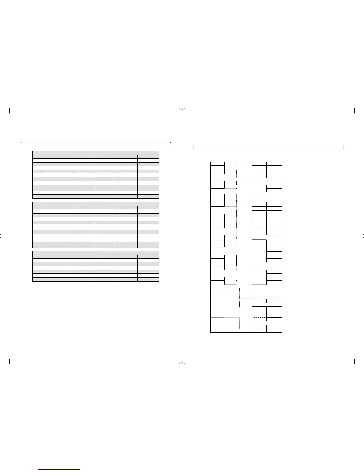
CM5000 Wiring Schematic (Alarm and Remote Start)
The CM5000 is the control module for all alarm and remote start combo units. This controller is universal
regardless of remote or antenna type.
( - ) Switch 3 Gray 1 Red 2 Green / White 1: ( + ) 12v Constant 2: ( + ) Parking Light
( + ) Led 2 Gray 3 Red / White 4 White
3: ( + ) 12v Constant (Separate
Red/White prewired to 2
nd
Relay)
4: ( + ) Accessory
( - ) Ground 1 Gray / Black
CN9
Plug In
LED/Valet
Switch
(N/A on
V.SF)
5 Violet 6 Yellow
5: ( - ) When Armed prewired to
Starter Kill Relay
6: ( + ) Starter (prewired to Starter
Kill Relay)
CN1
7 Green and
Red
8 Black
7: ( + ) Ignition and (Separate Red
prewired to Starter Kill Relay)
8: ( - ) Ground
LED ( + )
2 Black /
White
LED ( - ) 1 Black
CN5
LED
1 Red 1: ( + ) 12v Back Up Battery
CN2
2 Black 2: ( - ) Ground Back Up Battery
LED 4 Yellow
( + ) 3 Red
ADS Blade Connector
(20 Pin Harness)
Please see the installation manual
for the Blade module for details.
This harness is not included with
the CM5000.
Knock 2 White
( - ) 1 Black
CN7
RPS
Sensor
1 Green /
White
2 Lt Blue 1: ( - ) Parking Lt. Output 2: ( - ) E-Brake Input
3 Red / Black
4 Lt. Blue /
White
3: ( - ) Starter Output 4: ( + ) Brake Input
5 Green 6 Violet / Black 5: ( - ) Ignition Output 6: ( - ) Trunk Input
( - ) 4 Black 7 White / Black 8 Red / White 7: ( - ) Accessory Output 8: ( - / + ) Door Input
( + ) 3 Red 9 Black
10 Brown /
White
9: ( - ) Status Out (GWR) 10: ( - ) Glow Input/Key Sensing
TX 2 White 11 Orange 12 Pink 11: ( - ) Rearm Output 12: ( - ) Slave/Closed Loop Input
RX 1 Yellow
CN8
Antenna
13 Orange /
White
14 Yellow /
Black
13: ( - ) Disarm Output 14: (AC) Tach / Alternator Input
15 White 16 Gray / Black 15: ( - ) Aux 1 Output 16: ( - ) Hood Input
CN3
17 Violet 18 Brown 17: ( - ) Aux 2 Output 18: ( + ) Siren Output
1st Stage Shock 4 Yellow
( + ) 3 Red
2nd Stage
Shock
2 White
None Future use
( - ) 1 Black
CN6
Shock
Sensor
2 Violet / White ( - ) Trunk release output
3 Orange /
Black
( - ) Second Unlock Output
4 Blue ( - ) Unlock Output
1st Stage 4 Grey / White
5 Blue / Black ( - ) Lock Output
( + ) 3 Red
CN4
None ( + ) 12v Constant Power
2nd Stage
2 Black /
White
( - ) 1 Black
CN10
Optional
Sensor
Input
1 ( + )
2 ( - )
2 Black
3 Data
1 Black /
White
CN11
Thermistor
CN12
RS232
4 Data
Green/White Loop
Cut=Auto Trans. Uncut=Manual
Trans.
Every control module has this wire
intact and must be cut for automatic
( + ) ( - )
Default
Door Trigger Polarity
Blade Cartridge Slot - Please
visit
www.idatalink.com/compustar
for compatibility and more
information. This slot is empty
and has a plastic cover that slides
off.
IMPORTANT: Manufacturer or
seller will have no responsibility for
any injuries and/or damages
caused by improper care of the
product such as decomposition,
conversion, and transform done by
a user voluntarily
( + ) ( - )
Default
Key Sense/Glow Plug Polarity
Jumpers
( + ) Parking
Lights
Trunk Release
Default
Behavior of CN1, Pin 2
Black
Pin 1
- Negative (-) ground.
nd
White
Pin 2
- 2 stage negative (-) input. (Instant trigger)
Red
Pin 3
- 12V positive (+) output.
st
Pin 4
Yellow - 1 stage negative (-) input. (Warn away)
Connector 7 (CN7), 4-Pin (Pre-wired RPS) (CM5000 Only)
Black
Pin 1
- Negative (-) ground.
White
Pin 2
- Negative (-) paging input.
Red Pin 3 - 12V positive (+) output.
YellowPin 4 - 9V positive (+) L.E.D. output.
Connector 8 (CN8), 4-Pin (Pre-wired Antenna Cable)
Yellow
Pin 1
- RX input. This wire receives the signal from remote.
White
Pin 2
- TX output. This wire transmits the signal to remote.
RedPin 3 – Constant 12V positive (+) output.
Pin 4 Black – Negative (-) ground.
Connector 10 (CN10), 4-Pin (Optional Sensor Input)
This connector provides optional sensor inputs. Most commonly used with proximity and tilt sensors.
Black
Pin 1
– Negative (-) ground.
nd
Black/White
Pin 2
- 2 stage negative (-) input. (Instant trigger)
Red
Pin 3
– 12V positive (+) output.
17
 Loading...