hood is opened while the alarm is armed. You can connect this wire to the hood pin supplied with
this kit, or to a wire in the vehicle that shows (-) only while the hood is open.
Violet
Pin 17
- Auxiliary 2 250mA negative (-) output. This is an optional output that can be changed to
trigger different devices like window modules or strobe lights.
Brown
Pin 18
- Siren 12V positive (+) output. Connect this wire to the (+) wire located on the siren. To
change siren output settings, review Option 3-07.
Connector 4 (CN4), 6-Pin
Not used
Pin 1
Violet/White
Pin 2
- Trunk release 250mA negative (-) output. This is an optional output that will
release the trunk. Use CN1, Pin 2 if the vehicle is equipped with a (+) trunk release. System will
unlock doors and disarm alarm prior to trunk release.
nd
Orange/Black
Pin 3
- 2 Unlock 250mA negative (-) output. This is an optional output that will provide
a (-) pulse for driver’s priority door lock. IMPORTANT: You must isolate the driver’s door and
turn on Option 1-3.
Blue
Pin 4
- Unlock 250mA negative (-) output. This is an optional output that will provide a (-) pulse for
unlocking doors. System will unlock doors and disarm alarm. IMPORTANT: You must reverse
polarity for (+) trigger door lock systems. For additional lock settings review Option Group
1
Blue/Black
Pin 5
- Lock 250mA (-) negative output. This is an optional output that will provide a (-)
pulse for locking doors. System will lock doors and arm alarm. IMPORTANT: You must reverse
polarity for (+) trigger door lock systems. For additional lock settings review Option Group
1.
Not used
Pin 6
Connector 5 (CN5), 2-Pin (Pre-wired LED)
Note: Do not mistake for Thermistor port.
Black
Pin 1
- L.E.D negative (-) ground.
Black/White
Pin 2
- L.E.D. 3V positive (+) output.
Connector 6 (CN6), 4-Pin (Pre-wired Shock Sensor) (CM5000 Only)
16
Connector 1 (CN1), 8-Pin
Pin 1
Red - Constant 12V positive (+) power input. This wire must be connected. The proper vehicle
wire will test (+) 12V at all times - while the key is in the off position, the on position and during
crank.
Green/White
Pin 2
– This is a dual-purpose wire that features selectable functionality thru the
trunk/light jumper on the control module. It is either a positive (+) parking light output or positive
(+) trunk output.
Default - Parking light positive (+) output. The proper vehicle wire will test (+) 12V when the
parking light switch is in the on position.
Optional – Trunk release positive (+) output. The proper vehicle wire will test (+) 12V when the
trunk release is triggered.
Red/White
Pin 3
- Constant 12V positive (+) power
input. This wire must be connected. The proper
vehicle wire will test (+) 12V at all times - while
the key is in the off position, the on position and
during crank.
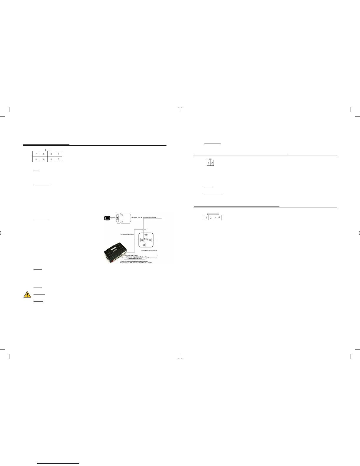
This pin also has a red/white wire that is pre-
wired to a relay. The short violet wire on Pin 85 is
the trigger input wire that determines the (+) 12V
output type of the long blue wire on Pin 30. For
example, connecting the negative (-) Ignition
output from Connector 3, to the short violet wire
coming off of the relay, will provide an additional
(+) 12V Ignition output from the long blue wire.
Pin 4
White – Accessory 12V positive (+) output. This wire must be connected to the vehicle accessory
/ HVAC blower motor wire. The proper wire will test 0V with the key in the off position, (+) 12V
while key is in the on position, 0V while cranking and back to (+) 12V when the key is returned to
the on position.
.
Violet
Pin 5
- 250mA negative (-) output when armed and during remote start (while running). This wire
is pre-wired to the anti-grind/starter-kill relay.
Caution: When this wire is being used to trigger aftermarket accessories it must be diode isolated.
Yellow
Pin 6
- Starter 12V positive (+) output. This wire is pre-wired to Pin 87a of the anti-grind/starter-
kill relay. This wire must be connected for remote start. The proper wire will test 0V with the key in
the off position, 0V while the key is in the on position and (+) 12V during crank.
There are two wires coming off of the relay; yellow/black and yellow. To utilize the anti-grind or
starter-kill features, the vehicles starter wire must be cut in half, otherwise, cut the relay out of the
harness and connect the yellow (Pin 6) directly to the vehicles’ starter wire.
13
st
Pin 4 Grey/White - 1 stage negative (-) input. (Warn away)
Connector 11 (CN11), 2-Pin (Pre-wired Thermistor)
Plug optional thermistor into this connector to monitor the vehicles’ temperature. It used display
temperature on two way LCD’s. IMPORTANT: New Thermistor plugs are blue 2 pin connectors on the
CM5 series but old white plug Thermistors will still work.
Black
Pin 1
- Thermistor
Black/WhitePin 2 - Thermistor
Connector 12 (CN12), 4-Pin (RS 232 Data Port)
This connector is used for updating control modules via www.compustar.com. You must also use this
port to flash ADS Blade bypass modules. This port provides simple connectivity of Fortin and iDataLink
bypass modules.
18
11
CM5200 Wiring Schematic (Remote Start)
The CM5200 is the control module for all remote start units. This controller is universal regardless of
remote or antenna type.
( - ) Switch 3 Gray 1 Red
2 Green /
White
1: ( + ) 12v Constant 2: ( + ) Parking Light
( + ) Led 2 Gray 3 Red/White 4 White
3: ( + ) 12v Constant Red / White
prewired to 2
nd
Relay
4: ( + ) Accessory
( - ) Led 1 Gray/Black
CN9
Plug In
LED/Valet
Switch
(N/A on
V.SF)
5 Violet 6 Yellow
5: ( - ) When Armed prewired to
Anti-Grind Relay
6: ( + ) Starter prewired to
Anti-Grind Relay
CN1
7 Green and
Red
8 Black
7: ( + ) Ignition Red prewired to
Anti-Grind Relay
8: ( - ) Ground
LED ( + ) Black / White
LED ( - ) Black
CN5
LED
ADS Blade Connector
(20 Pin Harness)
Please see the installation manual
for the Blade module for details.
This harness is not
included with the CM5200.
1 Green / White 2 Lt Blue 1: ( - ) Parking Lt. Output 2: ( - ) E-Brake Input
( - ) 4 Black 3 Red / Black
4 Lt. Blue /
White
3: ( - ) Starter Output 4: ( + ) Brake Input
( + ) 3 White 5 Green 6 Violet / Black 5: ( - ) Ignition Output 6: ( - ) Trunk Input
TX 2 Red 7 White / Black 8 Red / White 7: ( - ) Accessory Output 8: ( - ) Door Input
RX 1 Yellow
CN8
Antenna
9 Black
10 Brown /
White
9: ( - ) Status Out (GWR)
10: ( - ) Glow Input/Key
Sensing
11 Orange 12 Pink 11: ( - ) Rearm Output
12: ( - ) Slave/Closed Loop
Input
13 Orange /
White
14 Yellow /
Black
13: ( - ) Disarm Output
14: (AC) Tach / Alternator
Input
4 ( - ) 15 White
16 Gray /
Black
15: ( - ) Aux 1 Output 16: ( - ) Hood Input
3 ( + )
CN3
17 Violet 18 Brown 17: ( - ) Aux 2 Output 18: ( + ) Siren Output
2 Data
1 Data
CN12
RS232
1 Black / White
CN11
Thermistor
2 Black
( + ) 12v
Constant Power
None
( - ) Lock Output 5 Blue / Black
( - ) Unlock
Output
4 Blue
( - ) Second
Unlock Output
3 Orange /
Black
( - ) Trunk
release output
2 Violet /
White
Green/White Loop
Cut=Auto Trans. Uncut=Manual
Trans.
Every control module has this wire
intact and must be cut for automatic
Future use None
CN4
( + ) ( - )
Default
Door Trigger Polarity
( + ) ( - )
Default
Key Sense/Glow Plug Polarity
Jumpers
( + ) Parking
Lights
Trunk Release
Blade Cartridge Slot - Please visit
www.idatalink.com/compustar for
compatibility and more information. This
slot is empty and has a plastic cover that
slides off.
IMPORTANT: Manufacturer or seller will have
no responsibility for any injuries and/or
damages caused by improper care of the
product such as decomposition, conversion,
and transform done by a user voluntarily.
Default
Behavior of CN1, Pin 2
 Loading...