Instruction Manual
D103412X012
DVC6200f Digital Valve Controller
July 2013
1
Contents
Section 1 Introduction and
Specifications 3......................
Scope of Manual 3..............................
Instrument Description 3........................
Using this Manual 4.............................
Specifications 6................................
Related Information 10..........................
Educational Services 10..........................
Section 2 Installation 11.................
Installation 11.................................
Mounting 11...................................
DVC6200f Digital Valve Controller 11.............
DVC6205f Base Unit 14........................
DVC6215 Feedback Unit 16.....................
Sliding‐Stem Linear Actuators up to
210 mm (8.25 Inches) Travel 18...........
Fisher Rotary Actuators and Sliding‐Stem
Linear Actuators over 210 mm
(8.25 Inches) Travel 20...................
GX Actuators 22...........................
Quarter‐Turn Rotary Actuators 25............
Fisher 67CFR Filter Regulator 26.................
Pneumatic Connections 26.......................
Pressure 26...................................
Supply 27....................................
Output Connection 28......................
Special Construction to Support
Solenoid Valve Testing 29................
Vent 30..................................
Wiring and Electrical Connections 31..............
Connecting Fieldbus Wiring 31..................
Twisted‐Shielded Pair 32....................
Quick Connect Cable Entry 33...............
Remote Travel Sensor Connections 34............
Communication Connections 36.................
Simulate Enable Jumper 36.......................
Commissioning Tag 27..........................
Section 3 Basic Setup 39.................
Basic Setup 39.................................
Transducer Block Mode 39......................
Protection 39.................................
Device Setup 40...............................
Performance Tuner 44.........................
Section 4 Detailed Setup 45..............
Resource Block 45..............................
Transducer Block 62............................
Analog Output Function Block 113................
Proportional/Integral/Derivative
Function Block 126.............................
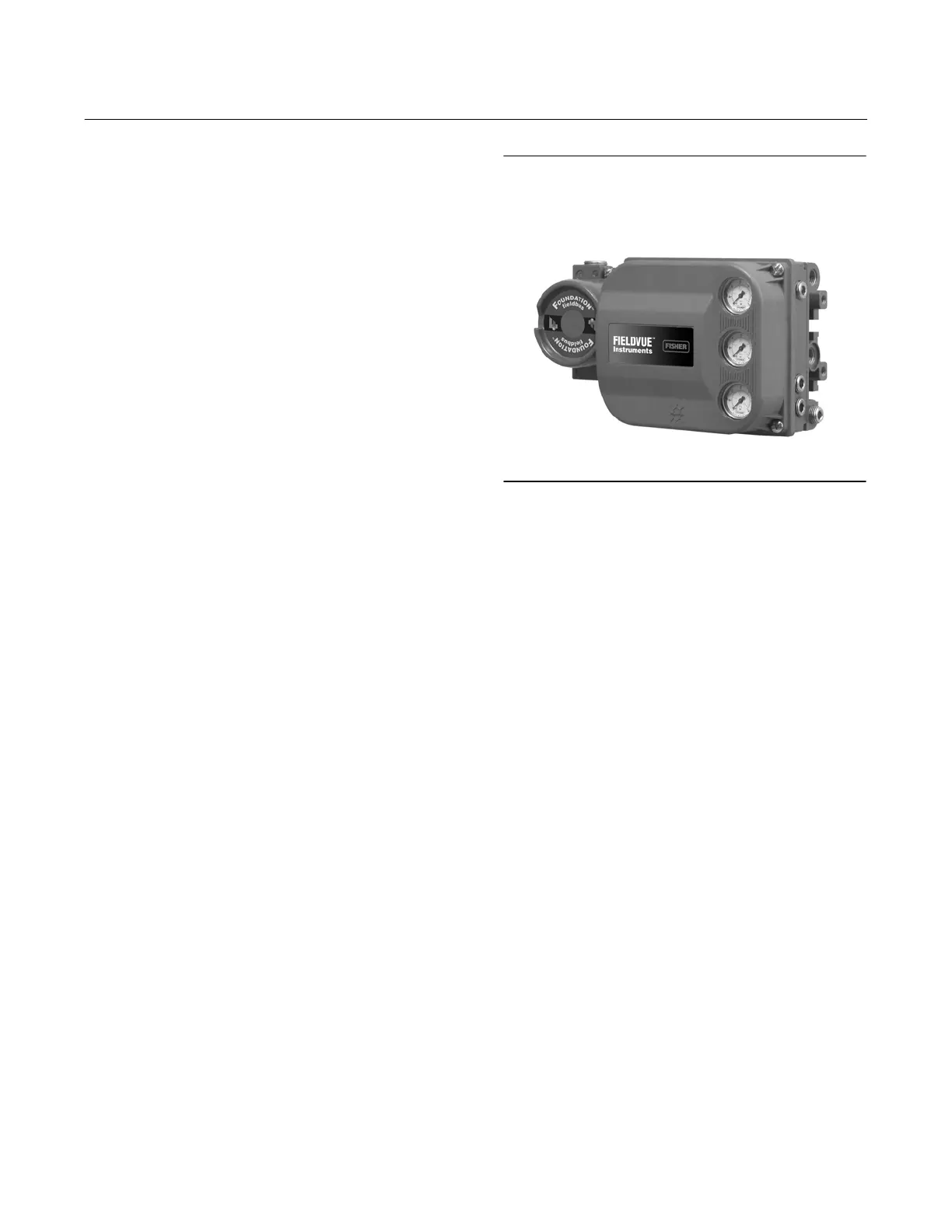
Figure 1‐1. FIELDVUE DVC6200f Digital Valve
Controller
W9713_fieldbus
Input Selector Function Block 145.................
Output Splitter Function Block 160................
Analog Input Function Block 171..................
Mulitple Analog Input Function Block 183..........
Discrete Output Function Block 189...............
Discrete Input Function Block 201.................
Section 5 Calibration 213................
Calibration Overview 213........................
Calibration 213.................................
Auto 214.....................................
Manual 214..................................
Relay 215....................................
Supply Pressure Sensor 216.....................
Pressure A or B Sensor 217......................
Section 6 Viewing Device
Variables and Diagnostics 219..........
View Lists 219..................................
Resource Block 219.............................
Device Diagnostics 220.........................
Device Variables 222...........................
Transducer Block 223...........................
Device Diagnostics 224.........................
Device Variables 229...........................
Section 7 Maintenance and
Troubleshooting 233..................
Replacing the Magnetic Feedback Assembly 234.....
Module Base Maintenance 234....................
Tools Required 234............................

 Loading...


