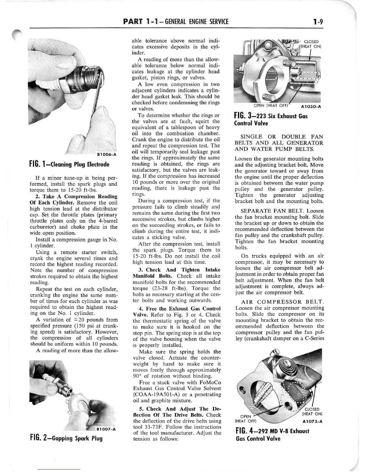
Bl006-A
FIG
_ l-Cleaning
Plug
Eledrode
If
a
minor
tune-up
is being per-
formed, install
the
spark
plugs
and
torque them to 15-20 ft-Ibs.
2.
Take
A Compression
Reading
Of
Each
Cylinder. Remove
the
coil
high tension lead
at
the
distributor
cap.
Set the throttle plates (prima
ry
throttle plates
on
ly on
the
4-barrel
carb
ur
etor)
and
choke
plate in
the
wide open position.
In
stall a compression gauge in
No.
1 cylinder.
Using a
remote
starter
switch,
crank the engine several times
and
record the highest reading recorded.
No
te the
number
of
compression
strokes required to
obtain
the highest
reading.
Repeat the test on
each
cylinder,
cranking the engine
the
same
num-
ber
of
tVncs for
each
cylinder as was
required to
obtain
the
highest
read-
ing
on
the
No.
1 cylinder.
A variation
of
± 20
pounds
from
specified pressure (150 psi
at
crank-
ing speed)
is
satisfactory.
However,
the compression
of
all cylinders
should be uniform
wi
thin 10 pounds.
A reading
of
more
than
the
allow-
FIG.
2-Gapping
Spark
Plug
PART
1-1-
GENERAL
ENGINE
SERVICE
able tolerance above
norm
al indi-
cates excessive deposits in
the
cyl-
inder.
A reading
of
more
than
the
a
ll
ow
-
able tolerance bel
ow
normal
indi-
cates leakage at the cylinder h
ead
gask.et, piston rings,
or
valve
s.
A l
ow
even
co
mpression in two
adjacent
cylinders indicates a cylin-
der
head gasket leak.
Thi
s should
be
checked
before
condem
ning
the
rings
or
valves.
To
determine
whether the rings
or
the valves
are
at
fault, squirt the
equivalent
of
a tablespoon
of
heavy
oil into the combustion
chamber.
Crank
the engine to distribute the oil
and repeat the compression tes
t.
The
o
il
wi
ll
temporarily seal leakage past
the
rings.
If
approximately the same
reading is obtained,
the
rings
are
sat
isfactory,
but
the valves are leak-
ing.
If
the compression has
in
creased
'10
pounds
or
more
over the original
reading, there
is
leakage past
the
rin
gs.
Dur
ing a co
mpre
ssi
on
test, if
the
pressure fails to climb steadily
and
remains the same
during
the first two
successive strokes,
but
climbs higher
on
the sllcceeding strokes,
or
fails to
climb
during
the entire test, it indi-
cates
a sticking valve.
After the compression test, install
the s
park
plugs.
Torque
them to
15-20 ft-Ibs.
Do
not
install the coil
hi
gh tension lead at this time.
3.
Check
And
Tighten
Inlake
Manifold
Bolts.
Check
a
ll
intake
manifold bolts for
the
recommended
torque
(23-28 ft-Ibs).
Torque
the
bolts as necessary
star
ting
at
the cen-
ter bolts
and
working
outw
ards.
4.
Free
the
Exha
ust
Gas
Co
ntrol
Valve. Refer to Fig. 3
or
4. Check
the thermostatic spring
of
the valve
to make sure it
is
hooked
on
the
stop pin.
The
spring stop is
at
the
top
of
the valve housing when the valve
is
proper
ly installed.
Make sure the spring holds
the
valve closed.
Actuate
the counter-
weight by
hand
to
make
sure it
moves freely through approximately
90°
of
rotation
without
binding.
Fr
ee
a stuck valve with
FoMoCo
Exhaust
Gas
Control
Valve Solvent
(COAA-19A501-A)
or
a penetrating
oil
and
graphite mixture.
5.
Check
And
Adjusl
The
De-
H,clion
Of
The
Drive
Belts.
Check
the deflection
of
the
dr
ive belts using
tool 33-73F. Follow
the
instructions
of
the
too
l
manufacturer.
Adju
st
the
tension as fo
ll
ows:
FIG.
3-223
Six
Exhaust
Gas
(ontrol
Valve
1-9
SINGLE
OR
DOUBLE
FAN
BELTS
AND
ALL
GENERATOR
AND
WATER
PUMP
BELTS.
Loosen
th
e gen
erator
mounting
bolts
and
the
ad
ju
sting
bracket
bolt.
Move
the
gen
erator
toward
or
away
from
the
engine until
the
proper
deflection
is
obta
ined between the
water
pump
pulley
and
the
generator
pulley.
Tighten
the
generator
adjusting
br
ac
ket
bolt
and the
mounting
bolts.
SEPARATE
FAN
BELT.
Loosen
the
fan
bracket
mounting
bolt. Slide
the
bracket
up
or
down
to
obtain
the
recommended
deflection between the
fan pu
ll
ey a
nd
the
cra
nk
shaft
pulley.
Tighten
the
fan
bracket
mounting
bolts.
On
tru
cks
equipped
with
an
air
compressor,
it
may
be
ne
cessary to
loosen
the
air
compressor
belt
ad-
justment
in
order
to
obtain
proper
fan
belt
adjus
tment.
When
the
fan belt
adjustme
nt
is
comp
lete, always ad-
just
the air
compressor
belt.
AIR
COMPRESSOR
BELT
.
Loo
sen
the
air
compressor
mounting
bolts. Slide
the
compressor
on
it
s
mounting
bracket
to
obtain
the
rec-
ommended
deflection between the
compressor
pulley
and
the
fan
pul-
ley (cra
nk
sh
aft
damper
on
a C-Series
FIG.
4-292
MD
v-a
Exhaust
Gas
(onlrol
Valve
 Loading...