FIG_
39-Cleaning
Ring
Grooves
Check
the piston to cylinder
bore
cl
ear
ance with a tension scale
and
ribbon (covered
under
"
Fitt
ing
Pi
s~
tons") and the ring side
clearance
(covered
under
"
Fittin
g
Pi
st
on
Rings").
R
ep
lace
piston
pins showing signs
of
fracture
or
etching
and
lo
r wear.
Check the piston pin
fit
in
the
piston
and rod.
Replace all rings
that
arc
s
cored,
chipped,
or
cracked.
Check
the
end
gap
and
side clearance.
It
is
good
pr
actice to always install new rings
when overhauling
the
engine.
Rin
gs
should
not
be
transferred
from
one
piston to another regardless
of
mile-
age.
REPAIRS
Fitting Pistons. Pistons
are
a vail-
a
bl
e for serv
ic
e in standard sizes
and
0.020, 0.030, 0.040, and 0.060-inch
oversize.
If the
clearance
is
great
er
than
th
e maxim
um
limit, recheck calcula-
tions to be s
ure
that
the
pr
o
per
size
piston has been selected before try-
ing a new piston.
If
the
clearance
is less
than
the
mini
mum
limit, rech
eck
calculations
before trying
another
piston.
If
none
can
be fitted, refinish the cylinder for
the next
si
ze piston.
When
a
piston
has
been
fitted,
mark
it
for
assembly in the
cylinder
to which it was fitted.
If
the
taper
and
out-of-round
con-
ditions
of
the cylinder
bore
are
within
limit
s,
new piston rings w
ill
give sat-
isfac
tory
service provided the piston
clearance in the cylinder
bore
is
within limits.
If
the
new rings
are
to
be
in
stalled in a used cylinder
that
has not
been
refinished,
remove
the
cylinder wall
"glaze."
To
fit a piston:
1. Calculate the s
iz
e piston to be
used by taking a
bore
check (Fig. 46).
2. Select
the
prop
er size
piston
to
provide the desired
clear
ance.
3.
Make
sure
the piston and cyl-
inder block
are
at
room
te
mperature
PART 1 -1 -
GENERAL
ENGINE
SERVICE
1-23
~I
o
3\
~
12
o
~
I
I
.,
~ 10
5
~
9
"
:> 6
"
'"
7
z
:1:
6
4
1;4
cc
POUNDS
ii
5
(E
XAMPLE)
4
3
2
o
\
\
1\
1\
\
\
-.002
\
\
\
1\ \
1\
\
\
\
- .001
\
1\
1\ \
1\ \
\
\
1\
\
\
\
\
,/
1\
l)(
1\ \
'\ 1/
V \
li
\
\
\
\
\:
\
\i \
-
0+
.001
\
V ·00
4
5
LX-
.004
V .0035
1'(,
r:;;
V·003
_
.002
5
YCJ\V
It
.002
V
~/
1\,00
15
"V
rY4..\
\
)<
\
1\ 1\ \
\ \ \
\
\
1\
\ \
'\
\
\
1\
1\ \ \
\
\
\ \
\
RIBBON
RIBBON
RIBBON
RIBBON
RIBBON
R
IB
BON
RIBBON
\
\
1\ \
\
4
POUNDS
(EXAMPLE)
.002
.003 .004 .005
CLEA
RA
NCE
IN
INCHES
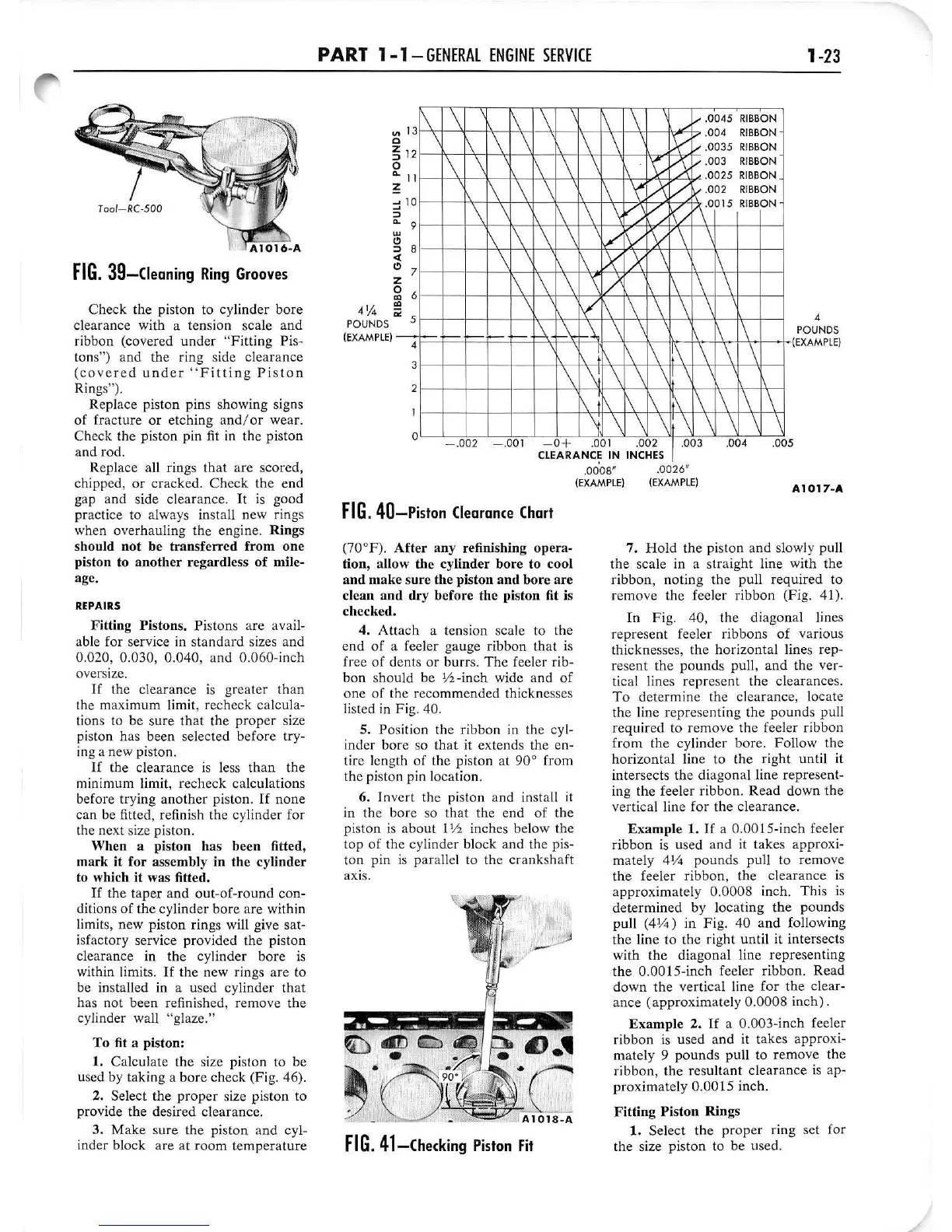
FIG.
40-Piston
Clearance
Chart
(70°F).
After
any
refinishing
opera-
tion
, allow
the
cylinder
bore
to cool
and
make
s
ur
e
the
piston
and
bore
are
clean
and
dry
before
the
piston fit
is
checked.
4.
Attach
a tension scale to the
end
of
a feeler
ga
uge
ribbon
that is
free
of
dents
or
burrs.
The
feeler rib·
bon
should
be 1/2 -in
ch
wide and
of
one
of the reco
mm
ended
thi
ckne
sses
listed
in
Fig.
40
.
5.
Po
si
ti
on the ribbon in the cyl-
ind
er
bore
so
that
it extends the e
n-
tire length
of
the piston at
90
°
from
the piston pin location.
6.
In
ve
rt the piston and
in
sta
ll
it
in the bore so
that
the e
nd
of
the
piston is about
l Y2 inches below the
top
of
the
cy
linder block
and
the pis·
ton
pin is parallel
to
the
crankshaft
axis.
FIG,
41-Checking
Piston
Fit
.
0008"
(EXAMPLE)
.
0026"
(EXAMPLE)
Al017-A
7. Hold the piston a
nd
slowly pull
the scale in a straight line with the
ribbon, noting
the
pull
required
to
remove
the feel
er
ribbon
(Fig. 41).
In
Fig. 40, the diagonal lines
represent
fe
eler ribbons
of
various
thicknesse
s,
the
horizontal
lines rep-
resent
the
pounds
pull,
and
the
ver-
ti
ca
l
li
nes represent the
clearances
.
To
determine
the clea
rance
, l
ocate
the line
representing
the
pounds
pu
ll
re
quir
ed to
remove
the feeler
ribbon
from
the
cylin
der
bo
re.
Follow
the
horizontal
line to the right until it
intersects the
diagona
l line represent-
ing the feeler ribbon. R
ea
d
down
the
vertical line for the cl
earance.
Example 1.
If
a
O.OO
IS-inch
feeler
ribbon
is used
and
it
takes
approxi-
mately
414
pounds
pull to
remove
the
feeler ribbon, the
clearance
is
approximately
0.
0008
inch.
Thi
s is
determined
by
locating
the
pounds
pull
(41
;';)
in F ig. 40
and
following
the line to the
ri
g
ht
until
it intersects
with
the
diagonal
line
repre
senting
the
0.00
l5-inch
feeler ribbon.
Read
down
the
vertical line
for
the
clear-
anc
e
(approx
im
ate
ly
0.0008
inch) .
Example
2.
If
a 0.003-inch feeler
ribbon
is used a
nd
it
takes
approxi
-
mately 9
pounds
pull to
remove
the
ribbon, the res
ultant
clea
ran
ce is ap-
proximately
0.00
15 inch.
Fitting
Piston
Rings
1.
Select the
proper
ring set fo r
the size piston to be used.
 Loading...