\
1-
20
GROUP
1-
ENGINES
AND
EXHAUST
SYSTEMS
Seat
Wid
th Scole
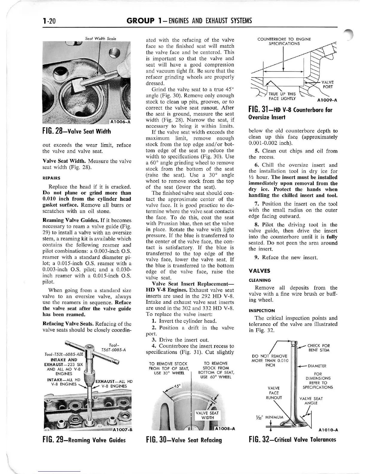
FIG.
28-Valve
Seat Width
out exceeds the wear limit, rcface
the va lve
and
va
lve seat.
Valve Scat Width. Meas
ur
e the valve
seat width (Fig. 28).
REPAIRS
Replace the
head
if it is cr
ac
ked.
Do n
ot
plane
or
g
rind
more
than
0.010 inch
from
th
e cylinder
head
gasket surface.
Re
move a
ll
burrs or
sc
ratch
es
wi
th an
oi
l stone.
Reaming Valve
Guid
es.
If
it becomes
n
ecessary
to
rea
m a
va
lve g
uide
(F
ig.
29) lo insta
ll
a valve with an oversize
stem, a reaming kit is ava
il
a
bl
e which
contains the follow
in
g reamer and
pilot
comb
i
nat
ions: a O.003-inch O
.S.
r
eamer
with a standard diameter pi-
lot; a D.DIS-inch
0.$.
reamer with a
0.003-in
ch
O.S. pilot; a
nd
a 0.030-
inch
reamer
with a
D.D
I5-i
nch
O.S.
pilot.
When
going from a stan
dard
size
valve to an oversize valve, always
use the r
eame
rs in sequence.
Ref
ace
th
e valve seat
aft
er
the
valve guide
has been reamed.
Refacing
Val
ve S
ea
ts. Refacing
of
the
val
ve
seats sh
ou
ld
be closely c
oo
rd in-
INTAKE
AND
EXHAUST
-223
SIX
AND A
LL
MD
v-a
E
NG
IN
ES
INTAKE
_A
LL
HD
v-a
EN
GIN
ES .......
...
L
~
T
ool-
T
56
T·6
085
·A
FIG.
29-Reaming
Valve
Guides
ated with the refacing
of
the valve
face so the finished seat will match
the
valve face a
nd
be centered.
This
is
important
so that the valve
and
seat wi
ll
have a good compression
and vacuum light fit.
Be
sure that the
refacer grinding wheels are properly
dressed.
Grind the val
ve
seat to a true 45°
angle (Fig. 30). Remove o
nl
y
enoug
h
stock to clean up pits, grooves,
or
to
correct
the
va
l
ve
seat m nou
t.
After
the seat is ground, measure the seat
wi
dt
h (Fi
g.
28).
Narrow
the seat, if
necessary to bri
ng
it within limit
s.
If
the val
ve
seat width exceeds the
maximum
li
mit, remove enough
stock from the top edge
andlo
r bot-
tom edge
of
the seat to reduce the
width to specifications (Fig. 30). Use
a 60° angle grinding wheel to remove
stock
from
the bottom
of
the
seat
(raise the seat). Use a 30° angle
wheel to remove stock from the t
op
of
the seat (lower the seat).
The
finished valve seat should con-
tact the approximate center
of
th
e
val
ve
face.
Jt
is
good practice to de-
termine where the valve seat contacts
the face. To do th
is,
coa
t the scat
with
Pr
Ll
ssian blue,
th
en set the valve
in
place. R
otate
the val
ve
with l
ig
ht
pressure.
If
the blue is transfe
rr
ed to
the ce
nt
er
of
th
e
va
l
ve
face, the con-
tact is satisfactory.
If
the
bl
ue is
transferred to the top ed
ge
of
the
valve face, lower the valve seat.
If
the b
lu
e
is
transferred to the bott
om
edge
of
(he valve face, raise the
val
ve
seat.
Valve Sc
at
Inse
rt
Replace
ment-
HD
V-S Engines. Exhaust valve seat
inserts are used
in
the 292 HD V-
8.
Intake and exhaust
va
l
ve
seat inserts
are
used
in
the 302 and 332
HD
V-
S.
To
replace the val
ve
insert:
1. Invert the cylinder head.
2. Position a
dr
ift in the valve
port.
3. D
ri
ve
the in
se
rt ou
t.
4.
Cou
nterbo
l'
e the insert recess to
spee
ifi
ca
ti
ons (Fi
g.
31
). Cut slightly
TO
REMO
VE
STOCK
FR
OM
TOP OF
SEA
T,
USE
30
0
W H
EE
L
TO
RE
M
OV
E
STOCK
F
RO
M
BOTTOM OF
SEA
T,
USE
60° W
HE
EL
FIG.
30-Valve
Seal
Refacing
COUN
T
ERBORE
TO
ENGINE
SPEC
IFICATIONS
A
1009-A
FIG
.
31-HD
V-8
(ounterbore for
Oversize Insert
below the old
counte
r
bore
dep
th
to
cl
ea
n up t
hi
s face (approx
im
ately
0.001-
0.002
inch
).
5. Clean out chips and o
il
from
the recess.
6.
Chill the oversize insert and
the installation tool in dry ice for
Y2
hou
r.
The inse
rt
must be installed
immediately
upon
re
mo
v
al
from the
dry
ice.
Prot
ect the hands when
handling
th
e chilled inse
rt
and
tool.
7.
Pos
ition the in
se
rt
on the tool
with the sma
ll
radius on the outer
edge facing outward.
S.
Pil
ot
th
e driving t
oo
l in the
va
lv
e guide,
the
n drive the insert
into the counterbore until it is fully
seated. Do not peen the area around
the
in
sert.
9. Reface the new inser
t.
VALVES
CLEANING
Re
move all deposits from the
valve with a fine
wi
re
bru
sh or bu
ff
-
ing whee
l.
INSPECTION
The critical inspecti
on
points and
toleran
ce
of the valve
are
ill
ustrated
in F i
g.
32.
DO
NO
T REMOVE
MO
RE
TH
AN 0.0 10
INCH
VALVE
FACE
RUNOUT
CH
ECK
fOR
B
EN
T ST
EM
DIAMETER
FOR
DIME NSIONS
REFER
TO
SPECIF
ICATIONS
A 1
01
O- A
FIG.
32-(rit
ical
Valve
Tolerances
 Loading...