---,;---ASSEMBLY-----
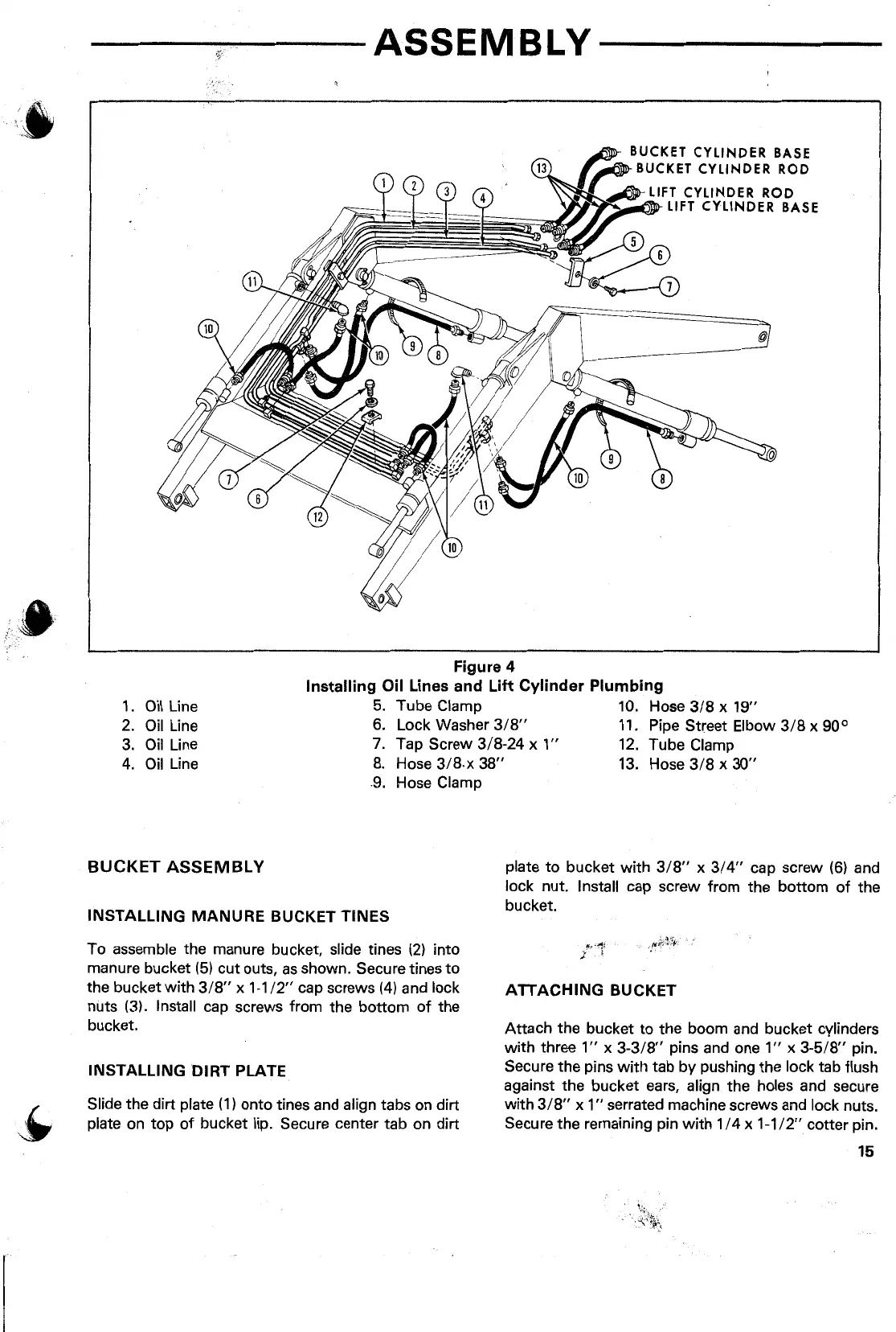
Figure 4
Installing Oil Lines and Lift Cylinder Plumbing
1.
Oil
Line
5.
Tube Clamp
10.
Hose
3/8
x 19"
2.
Oil
Line 6. Lock Washer
3/8"
11.
Pipe Street Elbow
3/8
x 90°
3.
Oil
Line
7.
Tap Screw 3/8-24 x
1"
12.
Tube Clamp
4.
Oil
Line
8.
Hose
3/8.x
38"
13.
Hose
3/8
x
30"
.9.
Hose Clamp
BUCKET ASSEMBLY
INSTALLING
MANURE
BUCKET TINES
To assemble the manure bucket, slide tines
(2)
into
manure bucket
(5)
cut outs,
as
shown. Secure tines
to
the bucket with
3/8"
x
1-1
/2"
cap screws
(4)
and lock
nuts (3). Install cap screws from the bottom
of
the
bucket.
INSTALLING
DIRT
PLATE
Slide the dirt plate (
1)
onto tines and align tabs on dirt
plate on top
of
bucket lip. Secure center tab on dirt
plate
to
bucket with 3/8" x 3/4" cap screw
(6)
and
lock nut. Install cap screw from the bottom
of
the
bucket.
ATTACHING
BUCKET
Attach the bucket
to
the boom and bucket cylinders
with three
1"
x
3-3/8"
pins and one
1"
x
3-5/8"
pin.
Secure the pins
with
tab by pushing the lock tab flush
against the bucket ears, align the holes and secure
with
3/8"
x
1"
serrated machine screws and lock nuts.
Secure the remaining pin
with
1 / 4 x
1-1
/2"
cotter pin.
15
 Loading...