3.2 Terminal arrangement and screw specifications
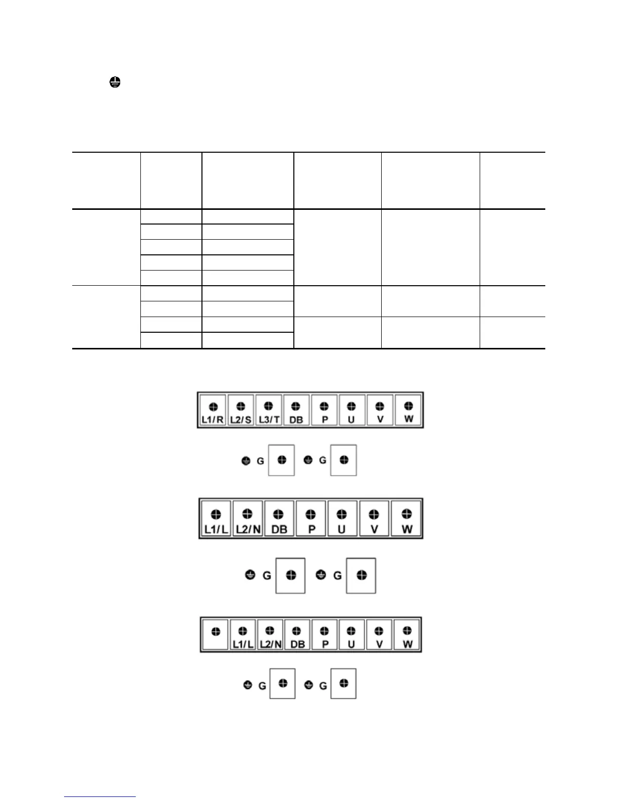
The figures below show the arrangement of the main and control circuit terminals which differ
according to inverter type. The two terminals prepared for grounding, which are indicated by the
symbol G in Figures A to C, make no distinction between the power supply side (primary circuit)
and the motor side (secondary circuit).
(1) Arrangement of the main circuit terminals
Table 3.1 Main Circuit Terminals
Power supply
voltage
Nominal
Ap
plied
m
otor(kW)
Inverter type
Terminal screw
size
Tightening torque
(N·m)
Refer to:
Three- phase
 Loading...


