3.4 Wiring for main circuit terminals and grounding terminals
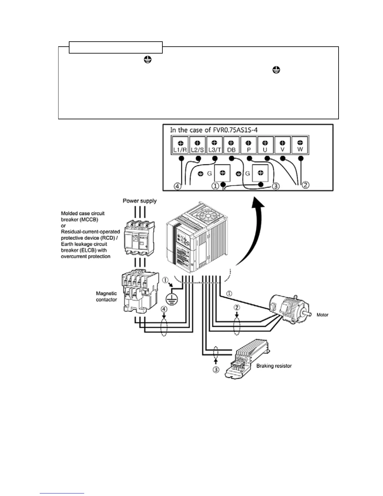
Follow the procedure below. Figure 3.1 illustrates the wiring procedure with peripheral equipment.
①
Grounding terminal G*
1
② Inverter output terminals (U, V, and W) and grounding terminal G*1
③ Braking resistor connection terminals (P and DB)*2
④ Main circuit power input terminals (L1/R, L2/S and L3/T) or (L1/L and L2/N)
*
1
Use either one of these two grounding terminals on the main circuit terminal block.
*
2
Perform wiring as necessary.
Figure 3.1 Wiring procedures for Peripheral Equipment
 Loading...


