EasyManua.ls Logo

Fujitsu AGYG14KVCA User Manual

Fujitsu AGYG14KVCA
567 pages
To Next Page IconTo Next Page
To Previous Page IconTo Previous Page
Page #386 background imageLoading...
Page #386 background image
18. Indoor unit installation precautions
NOTE: The information listed below are general precautions.
Some models also include items that do not apply.
18-1. Places where prohibited for use
Places where there is a danger of combustible gas leakage.
Places where sulfur gas, chlorine gas, acid, alkali, or other matter which effects equipment is gen-
erated.
Places where there is a lot of oil splash and steam such as kitchen or machinery room.
Places where machinery which generates high frequencies is used.
Ocean beaches and other areas where there is a lot of salt.
Places where carbon fibers or any kind of powder suspended in the air.
Inside of vehicles, ships, and other conveyances.
Places where voltage fluctuations are large such as a factory.
18-2. Points to remember when installing
The product shall be installed at a place which can withstand the weight and vibration of the in-
door.
To allow maintenance after refrigerant piping, drain piping, and the connection/installation of elec-
tric wiring, provide an maintenance space and an inspection port, as required.
Maintenance space is shown on "Dimensions" on page 35.
Be careful when installing the unit at the following places.
Condition Contents Countermeasures (Reference)
When the
ceiling is high.
If the indoor unit is installed where the installation height
given in the installation manual is exceeded, the
temperature difference between the floor and ceiling of the
room will be large and the heating effect will be poor.
Moreover, even if the indoor unit is installed within the
installation height, a similar phenomena will occur when
installed in a room in which the doors are opened and
closed frequently and hot air circulation is obstructed by
furniture such as desks or chairs.
1. Switch the setting to the high
ceiling mode.
2. Install a circulator.
3. Arrange the furniture in the
room so that it does not
obstruct the hot air.
When lower
level directly
contacts the
outside air.
When the lower level of the room is a semi-open space
such as warehouse or parking lot the surface temperature
of the flooring will become low and the radiation of cold
from the floor will increase.
In this case, even if the room temperature is suitable, you
may feel the foot level is cold.
When the
airflow
distribution is
poor.
When an indoor unit is installed in a position where the
outlet airflow will directly contact people, a draft may be
felt.
In addition, when there are obstructions in the path of the
intake and outlet airflow, the air distribution may become
extremely bad.
1. Adjust the louver fins or take
other measures matched to the
site.
2. Change the indoor unit outlet.
- 378 -
18-1. Places where prohibited for use
18. Indoor unit installation precautions
4-5 UNIT
MULTI-SPLIT TYPE
4-5 UNIT
MULTI-SPLIT TYPE

Table of Contents

Other manuals for Fujitsu AGYG14KVCA

Question and Answer IconNeed help?

Do you have a question about the Fujitsu AGYG14KVCA and is the answer not in the manual?

Fujitsu AGYG14KVCA Specifications

General IconGeneral
BrandFujitsu
ModelAGYG14KVCA
CategoryAir Conditioner
LanguageEnglish

Summary

AIR CONDITIONER DESIGN & TECHNICAL MANUAL

4-unit multi-split type, 5-unit multi-split type

Specifies the types of multi-split air conditioning systems covered in the manual.

Part 1. INDOOR UNIT

COMPACT CASSETTE TYPE

Details for indoor units with a compact cassette design, listing models.

MINI DUCT TYPE

Details for indoor units with a mini duct design, listing models.

SLIM DUCT TYPE

Details for indoor units with a slim duct design, listing models.

MEDIUM STATIC PRESSURE DUCT TYPE

Details for indoor units with medium static pressure duct type, listing models.

WALL MOUNTED TYPE

Details for indoor units with a wall-mounted type, listing models.

CEILING TYPE

Details for indoor units with a ceiling type, listing models.

FLOOR TYPE

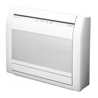
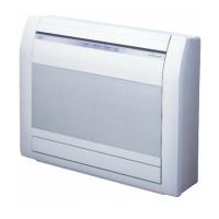
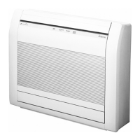
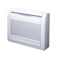
Details for indoor units with a floor type, listing models.

1. Model lineup

Overview of all available indoor unit models, categorized by type and capacity.

2. Specifications

Detailed technical specifications for various indoor unit types.

3. Wireless LAN control (for KGTF, KMCF, KETF, and KETF-B)

Information on system requirements and functions for wireless LAN control.

4. Dimensions

Technical drawings and dimensions for various indoor unit types.

5. Wiring diagrams

Electrical wiring diagrams for different indoor unit types.

6. Air velocity and temperature distributions

Airflow patterns and temperature distribution charts for various indoor units.

7. Fan performance

Fan performance curves (airflow vs. static pressure) for different indoor unit types.

8. Airflow

Tables detailing airflow rates (m³/h, l/s, CFM) for various fan speeds and modes.

9. Noise level curve

Octave band sound pressure level curves for different indoor unit types.

10. Electrical characteristics

Electrical specifications including power supply, input power, and current.

11. Safety devices

Information on safety devices like fuses, thermal protectors, and float switches.

12. External input and output

Details on external control inputs and outputs for various indoor unit types.

13. Group connection

Procedures and diagrams for connecting multiple indoor units in a group.

14. Remote controller

Overview, specifications, and system diagrams for various remote controller models.

15. Function settings

Guidance on adjusting product functions using DIP switches and remote controllers.

16. Accessories

List of included accessories for different indoor unit types.

17. Optional parts

Information on optional parts available for indoor units, including controllers and kits.

18. Indoor unit installation precautions

General precautions and points to remember for safe and proper indoor unit installation.

Part 2. OUTDOOR UNIT (4 UNITS TYPE)

1. Specifications

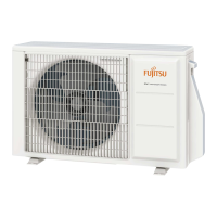
Detailed technical specifications for the 4-unit outdoor unit model.

2. Dimensions

Outline drawings and dimensions for the AOYG30KBTA4 outdoor unit.

3. Installation space

Guidelines for required installation space around the outdoor unit.

4. Refrigerant circuit

Diagram of the refrigerant circuit for the AOYG30KBTA4 outdoor unit.

5. Wiring diagram

Electrical wiring diagrams for the AOYG30KBTA4 outdoor unit.

6. Capacity table

Tables showing cooling and heating capacity combinations for indoor/outdoor units.

7. Capacity compensation rate for pipe length and height difference

Compensation rates for capacity based on pipe length and height difference.

8. Additional charge calculation

Guidelines for calculating additional refrigerant charge based on pipe length.

9. Airflow

Airflow rates (m³/h, l/s, CFM) for cooling and heating for the outdoor unit.

10. Operation noise (sound pressure)

Noise level curves and sound level check points for the outdoor unit.

11. Electrical characteristics

Electrical specifications including voltage, current, and wiring information.

12. Safety devices

Details on the protection mechanisms and safety devices of the outdoor unit.

13. Function settings

Methods for setting outdoor unit functions using DIP switches and push buttons.

14. Check and test

Procedures for check run, test run, error code identification, and pump down.

15. Accessories

List of accessories included with the AOYG30KBTA4 outdoor unit.

16. Outdoor unit installation precautions

Precautions and guidelines for safe and effective outdoor unit installation.

Part 3. OUTDOOR UNIT (5 UNITS TYPE)

1. Specifications

Detailed technical specifications for the 5-unit outdoor unit model.

2. Dimensions

Outline drawings and dimensions for the AOYG36KBTA5 outdoor unit.

3. Installation space

Guidelines for required installation space around the outdoor unit.

4. Refrigerant circuit

Diagram of the refrigerant circuit for the AOYG36KBTA5 outdoor unit.

5. Wiring diagram

Electrical wiring diagrams for the AOYG36KBTA5 outdoor unit.

6. Capacity table

Tables showing cooling and heating capacity combinations for indoor/outdoor units.

7. Capacity compensation rate for pipe length and height difference

Compensation rates for capacity based on pipe length and height difference.

8. Additional charge calculation

Guidelines for calculating additional refrigerant charge based on pipe length.

9. Airflow

Airflow rates (m³/h, l/s, CFM) for cooling and heating for the outdoor unit.

10. Operation noise (sound pressure)

Noise level curves and sound level check points for the outdoor unit.

11. Electrical characteristics

Electrical specifications including voltage, current, and wiring information.

12. Safety devices

Details on the protection mechanisms and safety devices of the outdoor unit.

13. Function settings

Methods for setting outdoor unit functions using DIP switches and push buttons.

14. Check and test

Procedures for check run, test run, error code identification, and pump down.

15. Accessories

List of accessories included with the AOYG36KBTA5 outdoor unit.

16. Optional parts

List of optional parts available for outdoor units.

17. Outdoor unit installation precautions

Precautions and guidelines for safe and effective outdoor unit installation.

Related product manuals