En-14
(1) Connecting the power supply cable
Caution when wiring cable
1) Use crimp-type terminals with insulating sleeves as shown in the fi gure to con-
nect to the terminal block.
2) Securely clamp the crimp-type terminals to the cables using an appropriate tool
so that the cables do not come loose.
3) Use the specifi ed cables, connect them securely, and fasten them so that there
is no stress placed on the terminals.
4) Use an appropriate screwdriver to tighten the terminal screws. Do not use a
screwdriver that is too small, otherwise, the screw heads may be damaged and
prevent the screws from being properly tightened.
5) Do not tighten the terminal screws too much, otherwise, the screws may break.
6) See the table for the terminal screw tightening torques.
Strip 10 mm
Cable
Screw with
special washer
Ring terminal
Terminal block
Ring terminal
Sleeve
Screw with
special washer
Ring terminal
Cable
Ring terminal: M8
Earth (Ground)
cable
Cable clamp
70 to 80 mm
90 to 100 mm
Use a ring terminal to connect the electric cables to the power supply terminal *
board.
(2) Connecting the transmission cable
Sealing transmission cable
Connect both ends of the sealed wires of the transmission cable to the earth terminal
of the equipment or to the earth screw near the terminal.
Be very careful that the screws are not overly tightened as the wires may snap and
the terminal may be damaged.
Wind with insulation tape to
prevent short circuit
Use one side of the
twisted-pair cable
Connect both ends of sealed
cable to earth.
Be sure to use one side of a twisted-pair cable when using transmission cable with 2
sets of twisted-pair cables.
RB
IN
Cable clip
Cable tie
(Accessory)
40 mm or more
8 to 10 mm
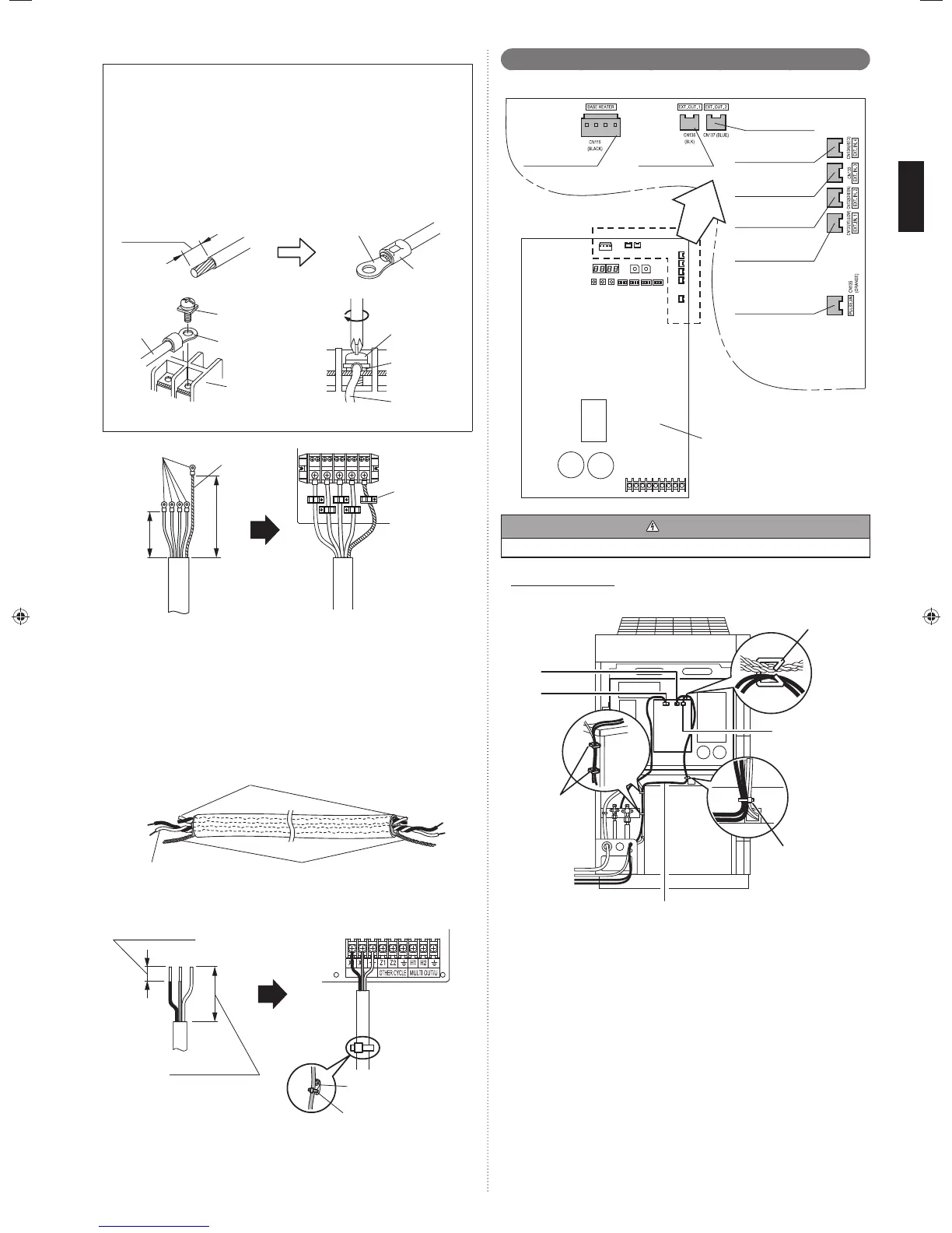
External input and external output6. 7.
Terminal position6. 7. 1.
Output 2
(CN137: Blue)
Base heater
(CN115: Black)
Output 1
(CN136: Black)
Input 4
(CN134: Red)
Input 3
(CN133: White)
Input 2
(CN132: Green)
Input 1
(CN131: Yellow)
Input 5
(CN135: Orange)
Outdoor unit PC board
CAUTION
Do not bundle the cable for base heater with other cables.
(Example)
In case of Outdoor unit
Insert the connector to CN136 (Black) and CN137 (Blue) of control PC board. (1)
Fix it to the wire with the attached cable tie.(2)
Clamp
CN137
(Blue)
CN115
(Black)
Cable tie
(Accessory)
Wire
▪ Do not clamp the base heater cable.
Clamp
CN136
(Black)
External input terminal6. 7. 2.
Service parts: EXTERNAL INPUT WIRE A (9368777005)
Setting to low noise mode, outdoor unit operation peak control setting, emergency/•
batch stop and electricity meter pulse are possible from the outside.
Except for wattmeter pulse reception (CN135) among external input terminals, only •
the Master unit is effective.
Wiring method and specifi cations
A twisted pair cable (0.33 mm*
2
(22AWG)) should be used. Maximum length of
cable is 150 m.
Use an external input and output cable with appropriate external dimension, de-*
pending on the number of cables to be installed
For each input, pin No.1 is of positive polarity and pin No.2 is of ground level.*
9378945104-01_IM.indb Sec1:149378945104-01_IM.indb Sec1:14 2013-3-12 14:08:262013-3-12 14:08:26

 Loading...


