En-15
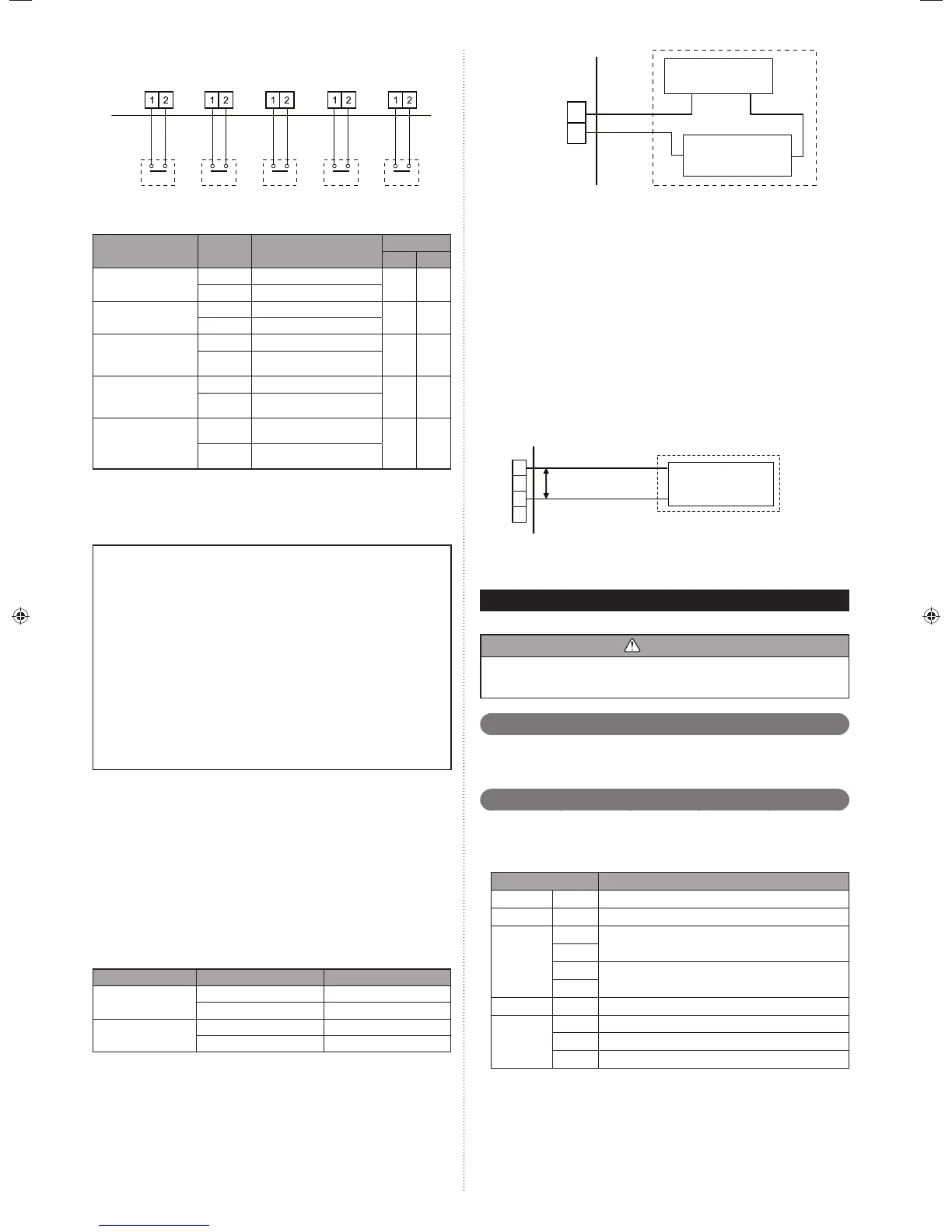
connected unit connected unit
connected unit connected unit connected unit
CN131
(Yellow)
CN133
(White)
CN132
(Green)
CN134
(Red)
CN135
(Orange)
P. C .B
Input 1
Input 3Input 2
Input 4
Input 5
Operation behavior
Each input terminal works as follows.
Connector Input signal Status
Outdoor unit
Master Slave
Input 1
CN131 (Yellow)
OFF Normal operation
O
ON Low noise mode operation
Input 2
CN132 (Green) *1
OFF Cooling priority
O
ON Heating priority
Input 3
CN133 (White)
OFF Normal operation
O
ON
Outdoor unit operation peak
control
Input 4
CN134 (Red)
OFF Normal operation
O
ON
Batch stop or Emergency stop
operation *2, *3
Input 5
CN135 (Orange) *4
No pulse
No information from electricity
meter
OO
Pulse
Power usage information from
electricity meter
Slave unit can connect only input5 (CN135).
The operations of each input terminal and the selection of function are set with the
push button on the PC board of outdoor unit. About the setting, please refer to 7.4.
Push button setting.
Note :
*1: The "external input priority mode" must be set by pressing push button on PC
board of outdoor unit.
*2: Batch stop or Emergency stop pattern can be selected by outdoor unit PC
board push button.
*3: The emergency stop function mounted in the V-II does not guarantee the
regulations of each country. For this reason, suffi cient checking is necessary
regarding use.
Especially, since the fact that the equipment may not be emergency-stopped
in the case of breaking of the wiring to the external input terminals and com-
munication line, communication error due to noise, VRF external input circuit
trouble, etc. must be considered, the provision of double measures that add
direct interruption of the power supply by switch, etc. is recommended as a
precaution.
*4: Pulse input to CN135 must be width 50ms or more, and must be interval 50ms
or more.
External output terminal6. 7. 3.
Service parts : EXTERNAL INPUT WIRE A (9368777005)
You can detect the operation condition of outdoor unit and the abnormal situation •
of both indoor and outdoor unit.
The external output terminal is only valid for Master Unit.•
Wiring method and specifi cations
Error status (Master unit only)
This output indicates the outdoor unit and connected indoor unit's "Normal" or "Error"
status.
Operation status (Master unit only)
This output indicates the outdoor unit's "Operation" status.
Connector Output voltage Status
CN136 (Black)
0 V Normal
DC 12 to 24 V Error
CN137 (Blue)
0 V Stop
DC 12 to 24 V Operation
1
2
+
+ -
*5
*6
*7
P. C .B
CN136
(Black)
or CN137
(Blue)
DC power supply
(External) 12 to 24 V
Connected load
(Operation Indicator or
Error Indicator)
connected unit
5: Provide a DC12 to 24 V power supply. *
Select a power supply capacity with an ample surplus for the connected load.
6: The allowable current is 30 mA or less. *
Provide a load resistance such that the current becomes 30 mA or less.
7: Polarity is [+] for pin 1 and [-] for pin 2. Connect correctly.*
Do not impress a voltage exceeding 24 V across pins 1-2.
A twisted pair cable (0.33 mm*
2
(AWG22)) should be used. Maximum length of
cable is 150 m.
Use an external input and output cable with appropriate external dimension, de-*
pending on the number of cables to be installed.
Base heater terminal6. 7. 4.
Service parts : WIRE WITH CONNECTOR (9708642000)
This is the output signal for base heater. Output signal ON, when the outdoor tem-
perature goes down below 2°C, and signal OFF at the outdoor temperature 4°C.
1
2
3
4
P. C .B
CN115
(Black)
*8
AC240 V
(For rated 415 V power supply)
Cable
(0.82 mm
2
(18AWG))
Base heater *9
8: Connect to pin 1 and pin 3. No connection pin 2 and pin 4.*
9: The allowable current is 1 A or less.*
FIELD SETTING7.
CAUTION
Discharge the static electricity from your body before setting up the DIP switches.
Never touch the terminals or the patterns on the parts that are mounted on the
board.
Field setting switches7. 1.
Remove the service panel of the outdoor unit and the cover of the electrical compo-
nent box to access the PC board of the outdoor unit.
PC board switches for various settings and LED indicators are shown in the fi gure.
DIP switch setting7. 2.
List of Settings7. 2. 1.
SET3 and SET5 must be set for the DIP switch.
Confi gure the settings before turning on the power. Settings for SET1, SET2, and
SET4 DIP switches are factory default ones. Do not change them.
DIP Switch Function
SET1 1-4 Forbidden
SET2 1-4 Forbidden
SET3
1
Outdoor unit address setting
2
3
Setting for number of slave units
4
SET4 1-4 Forbidden
SET5
1-2 Number of outdoor units installed
3 Forbidden
4 Terminal resistor setting
9378945104-01_IM.indb Sec1:159378945104-01_IM.indb Sec1:15 2013-3-12 14:08:262013-3-12 14:08:26

 Loading...


