En-16
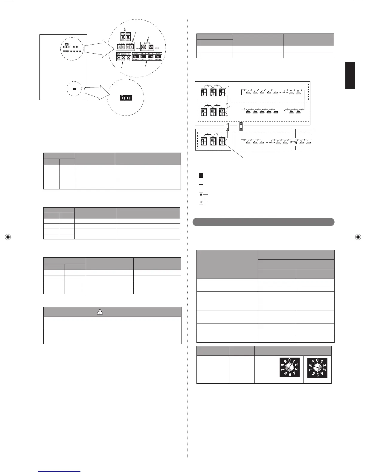
X 10 X 1
5'6
7 Segment
LED indicator
Push button
LED lamp
Rotary switch
Outdoor unit PC board
DIP switch
Settings to be confi gured locally7. 2. 2.
Outdoor unit address setting(1)
When 2 or 3 outdoor units are installed to 1 refrigerant system, set the address for
each outdoor unit.
Set the address for all outdoor units.
SET3
Outdoor unit address Remarks
12
OFF OFF 0 Master unit (Factory setting)
OFF ON 1 Slave unit 1
ON OFF 2 Slave unit 2
ON ON - Forbidden
Nu(2) mber of slave units setting for outdoor unit
Set the number of slave units connected to 1 refrigerant system.
Set only the master unit.
SET3
Number of connectable
outdoor units
Remarks
34
OFF OFF 0 Master unit only (Factory setting)
OFF ON 1 1 slave unit connected
ON OFF 2 2 slave unit connected
ON ON - Forbidden
Number o(3) f outdoor units installed
The number of outdoor units installed in 1 refrigerant system must be set.
Set for all outdoor units.
SET5
Number of outdoor units Remarks
12
OFF OFF 1 (Factory setting)
OFF ON 2 -
ON OFF 3 -
ON ON - Forbidden
Terminal resistor setting7. 2. 3.
CAUTION
Be sure to set the terminal resistor according to specifi cations.
Set the terminal resistor for every network segment (NS).
If terminal resistor is set in multiple devices, the overall communication system
may be damaged.
If terminal resistor is not set in a device, abnormal communication may occur.
Be sure to• set 1 terminal resistor in a network segment. You can set the terminal
resistor at the outdoor unit or signal amplifi er.
When settin• g the terminal resistor of a signal amplifi er, refer to the installation
manual of the signal amplifi er.
When settin• g multiple terminal resistors, take note of the following items.
How many network segments are there in a VRF system?
①
Where will you set the terminal resistors in a network segment? (Condition for 1
②
segment: Total number of outdoor and indoor units and signal amplifi ers is less
than 64, or the total length of the transmission cable is less than 500m)
How many outdoor units are connected to 1 refrigerant system?
③
Confi gure the setting (DIP switch SET5) of the terminal resistor of the outdoor units as
shown below from conditions
1
to
3
.
SET5
Terminal resistor Remarks
4
OFF Disable (Factory setting)
ON Enable -
Figure: Terminal resistor setting
NS2 (Network segment 2)
NS3 (Network segment 3)
NS4 (Network
segment 4)
NS1 (Network segment 1)
(Set terminal resistor at outdoor units)
Master unit
Master unit
Master unit
Refrigerant system1
Refrigerant system2
Refrigerant system3
Terminal resistor: off
Terminal resistor: on
Terminal resister: on
About the setting of terminal resistor
Outdoor unit (Master unit)
Install
Do not install
:on
:off
Signal amplifi er
Rotary switch setting7. 3.
The rotary switch (REF AD) sets the refrigerant circuit address of the outdoor unit.
Confi gure the settings only on the master unit of a refrigerant system.
If multiple refrigerant systems are connected, set the rotary switch (REF AD) as
shown in the table below.
Refrigerant circuit address
Rotary Switch Setting
REF AD
×10 ×1
000
101
202
303
404
・・・
・・・
97 9 7
98 9 8
99 9 9
Setting Setting range Type of switch
Refrigerant circuit
address
0–99
Setting
example
63
REF AD × 10 REF AD × 1
Rotary Switch (REF AD×1): Factory setting "0"
Rotary Switch (REF AD×10): Factory setting "0"
9378945104-01_IM.indb Sec1:169378945104-01_IM.indb Sec1:16 2013-3-12 14:08:272013-3-12 14:08:27

 Loading...


